Hi,
I am using a RDC6445G and appear to be having an issue in my Y axis.
Everything lines up beautifully in the X axis but when the laser returns to complete a new layer in the same position the Y axis seems to have stepped to far down.
Hopefully my image explains this better.
I do have slightly different numbers for my step settings however matching them up didn’t seem to fix the issue.
I have tripple checked my file and am sure it is not what is causing the issue.
Thanks.
Angus
Have you calibrated your axes to check the accuracy of your settings?
Other possibilities include skipping steps due to high acceleration / velocity, belt slop, low holding current, improperly set stepper driver DIP switches.
I’ll chime in on the calibration, and raise you a skew test.
Cut as large rectangle from a piece of paper as you have room for, I used some old wrapping paper, but add a dashed line down the middle.You want as large a rectangle as possible for accuracy. Enter your what it is and what it should be values and double check.
Now for that dashed line. Fold the paper on the dashed line and see if your corners come out even. If they do, your gantry and X movement are square to your Y rails. If not, the difference is what you are out of square, or skewed, by.
2 Likes
Thanks for the helpful info, I think Dave may be on to something but I wont be able to run that test for a few days. 
I ran the calibration checks and I didnt see anything that required changes, I’ll post the photos incase your eye is better than mine.
I dont think it’s skipping or belt slop as it is very consistent.
I’ll try the paper test and let you know.
Thanks
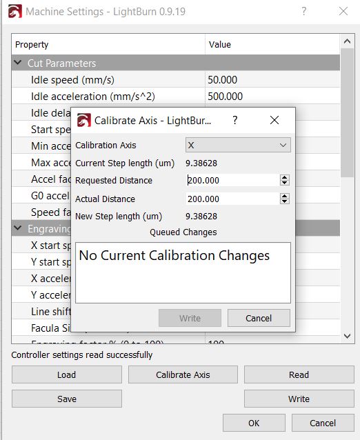
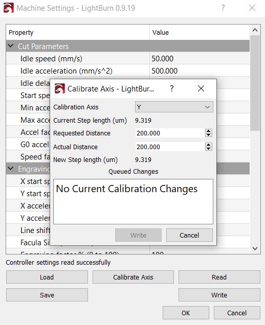
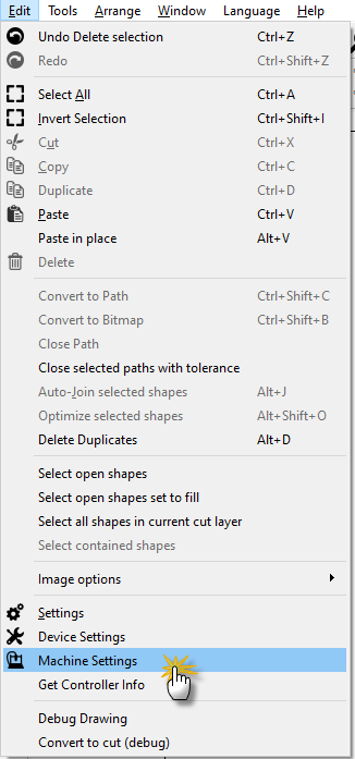
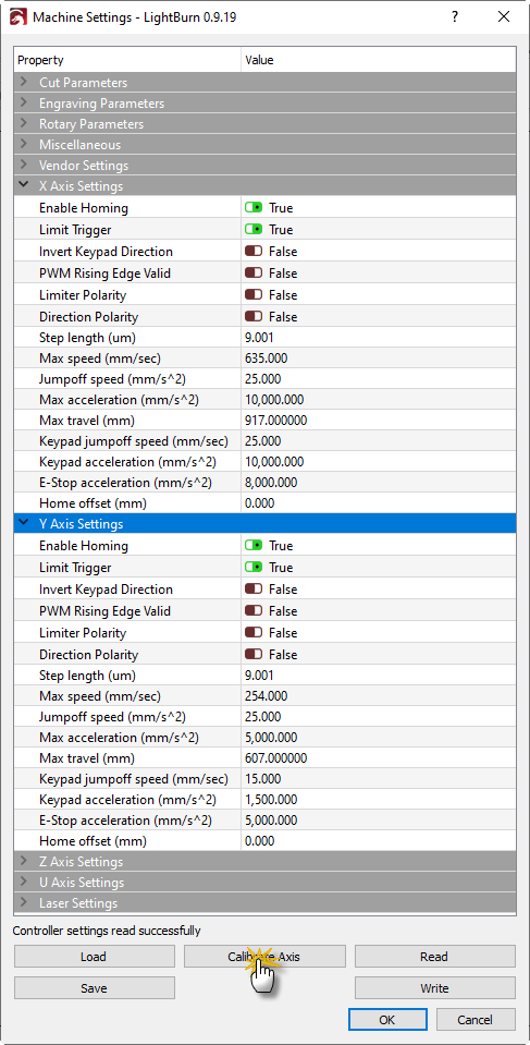
There is nothing to verify in those pictures of the axis calibration tool you provided. To check calibration you would do the following as an example:
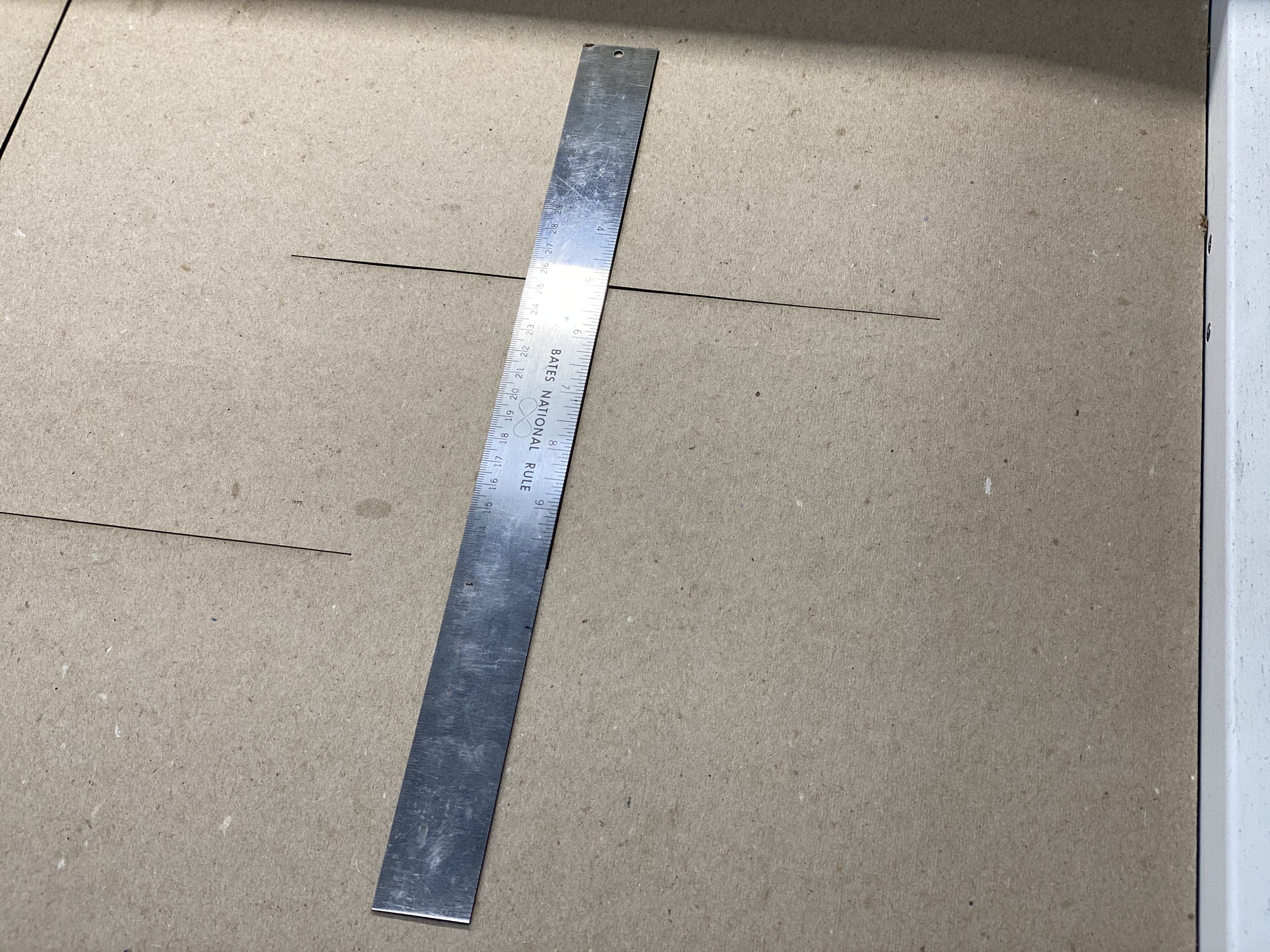
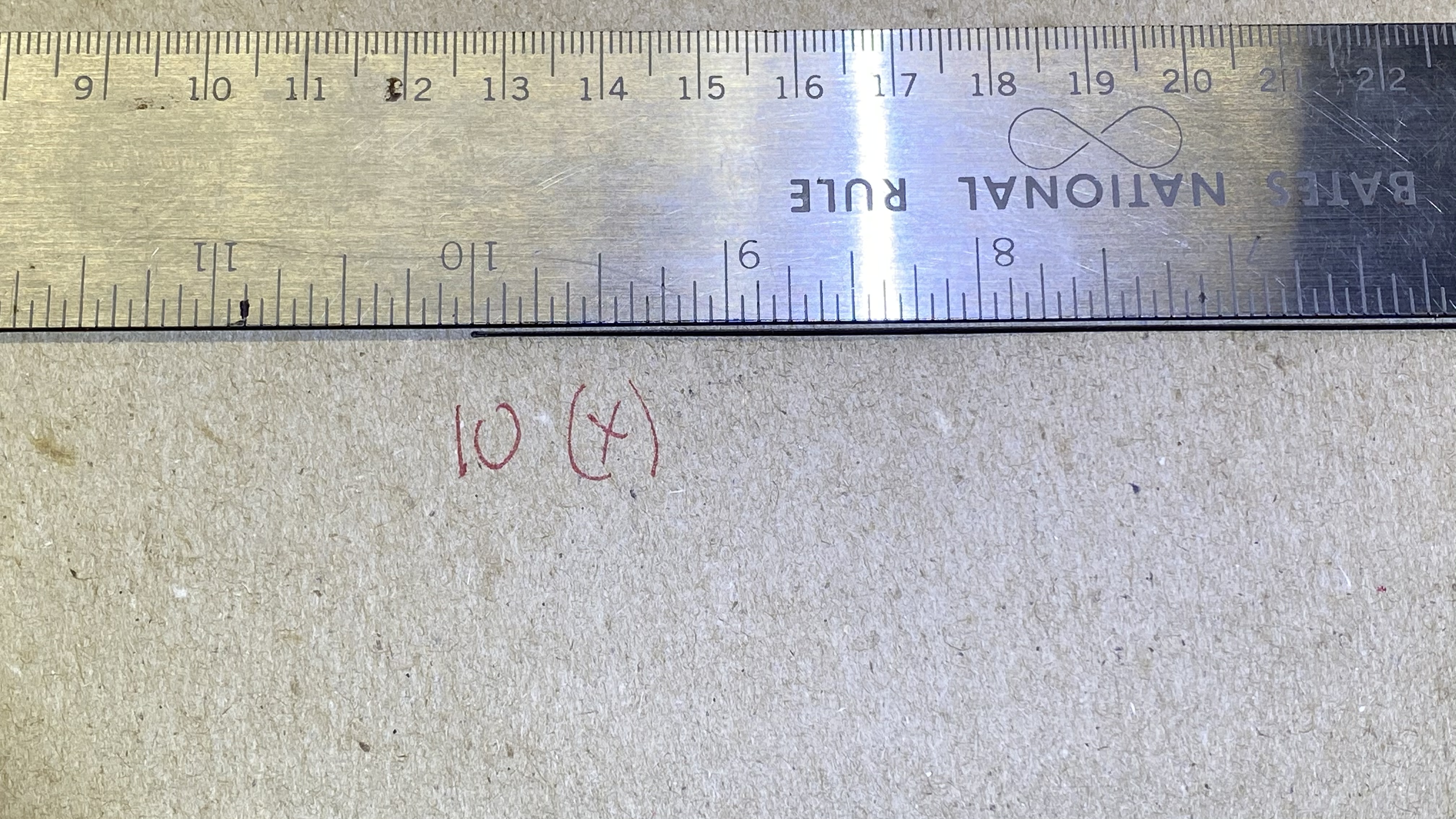
Draw a cross hair such as 10 inches on X and 10 inches on Y. Then run this job on your machine. Measure the resulting lines. In this example, X looks good, but look at Y:
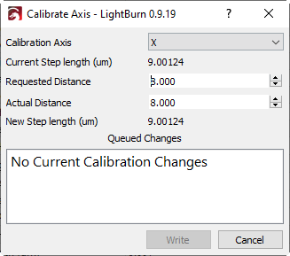
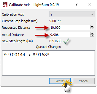
The Calibrate Axis utility is a great function that, once you have drawn that cross hair, calculates the corrective adjustment in your step length. So for Y I have the following input parameters of 10 (inches) that I expected my Y line to have been and 9.906 (inches) that was measured with the ruler. LightBurn calculates the correction in my step length from 9.00144 to 8.91683. But I must click on write to accept that calculated correction.
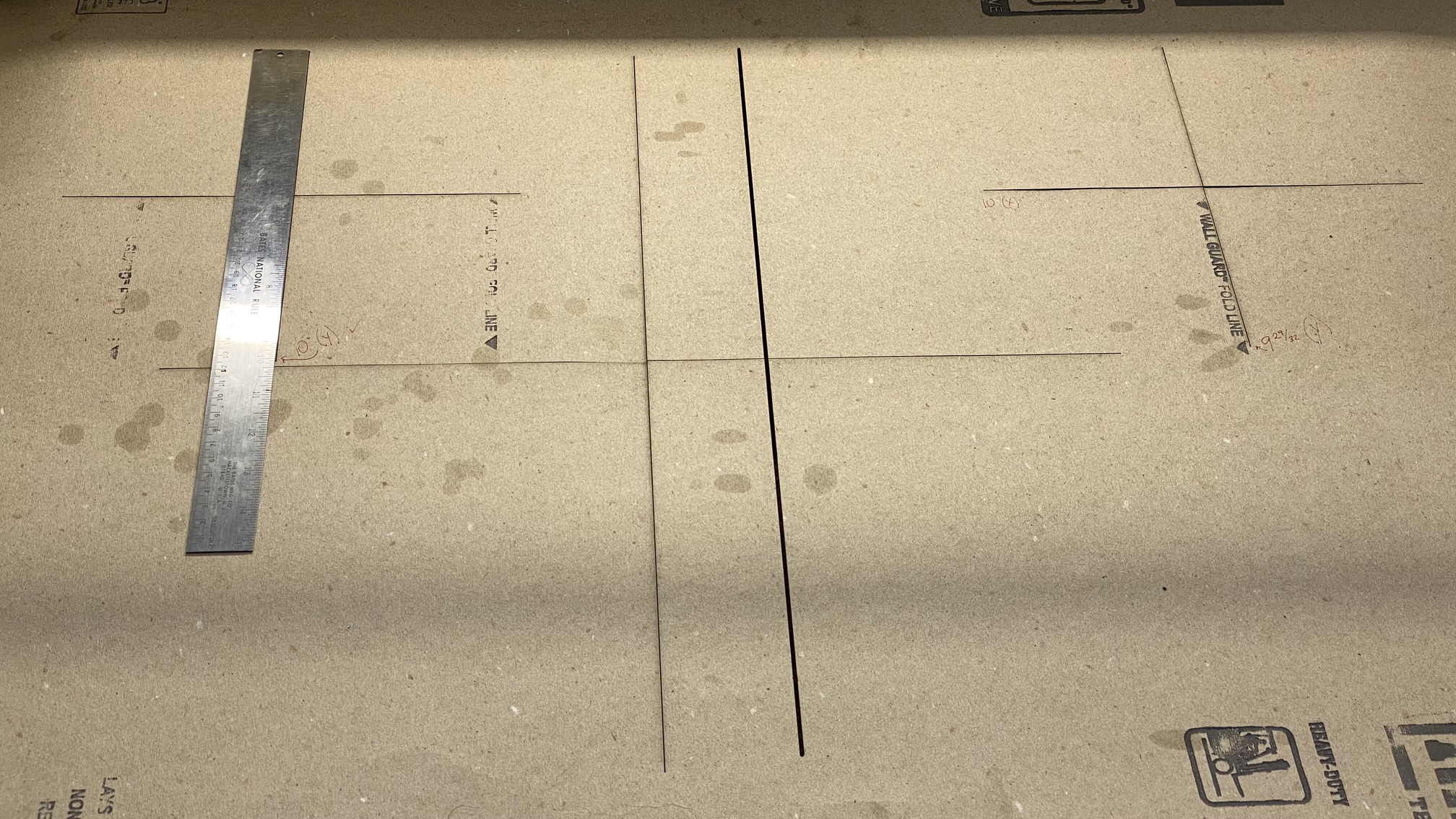
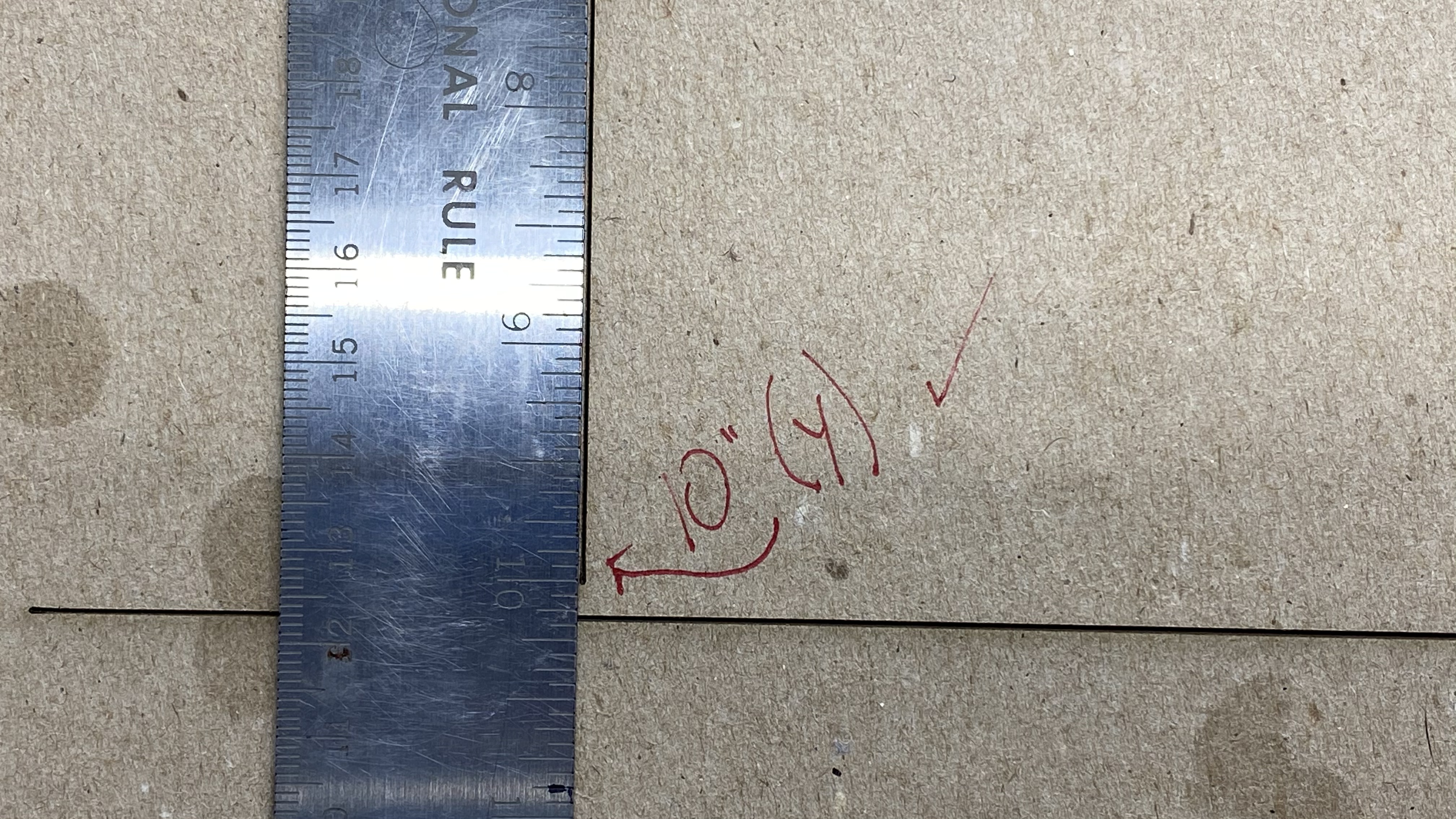
And with that, I can test my cross hair again:
1 Like
Jeff, My apologies.
I shall run the test properly and get back to you.
Cheers
Stroonzo, the advantage of the large square over the crossed lines is the added skew test all at the same time. All too many people have never checked their skew, but wonder why some parts don’t fit together the way they should. Usually it’s not much, but for tight inlay work and such it can mean the difference between a piece fitting, or it being wasted. On my 500 x 700 bed, I was out by a little under 3mm across the 700mm. Something that small will not be detectable by eye, but will show up when you fold the paper.
3 Likes
@Dave01, absolutely I agree with your recommendation (even gave it a like as it is a good process you laid out).
1 Like
Thanks for the like. I chuckle at the guys that will only cut a square as large as their calipers will measure. I’ll take a 680mm square and a good tape measure over a 150mm square and a caliper to check my steps any day… as long as I have my glasses on.
1 Like
Hey,
Firstly let me thank you both for the suggestions and help.
Unfortunately I don’t have access to my laser for a few days to run the paper test and thought maybe a better explanation of the problem may help to narrow down exactly what my issue is.
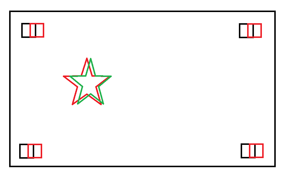
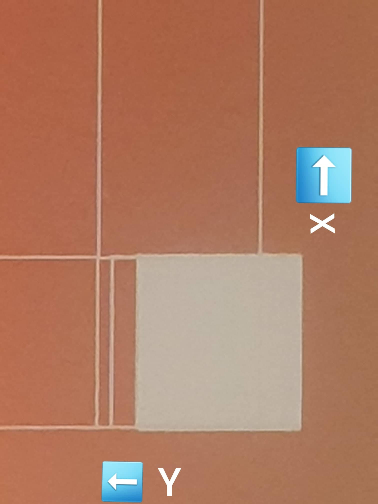
The small black squares are where my file says the red square should print and the red square is where they actually printed. If it was a skew or square issue wouldn’t I expect to see different displacement amounts in each corner., from memory they were all around 2mm off to the right.
The red star is where I tried to make a cut however I used an incorrect power/speed setting and didn’t make it all the way through, I then started the cut again ensuring that nothing moved and it cut the green star.
Again if it was a skew issue Id expect it to be off consistently not gradually creeping to the right.
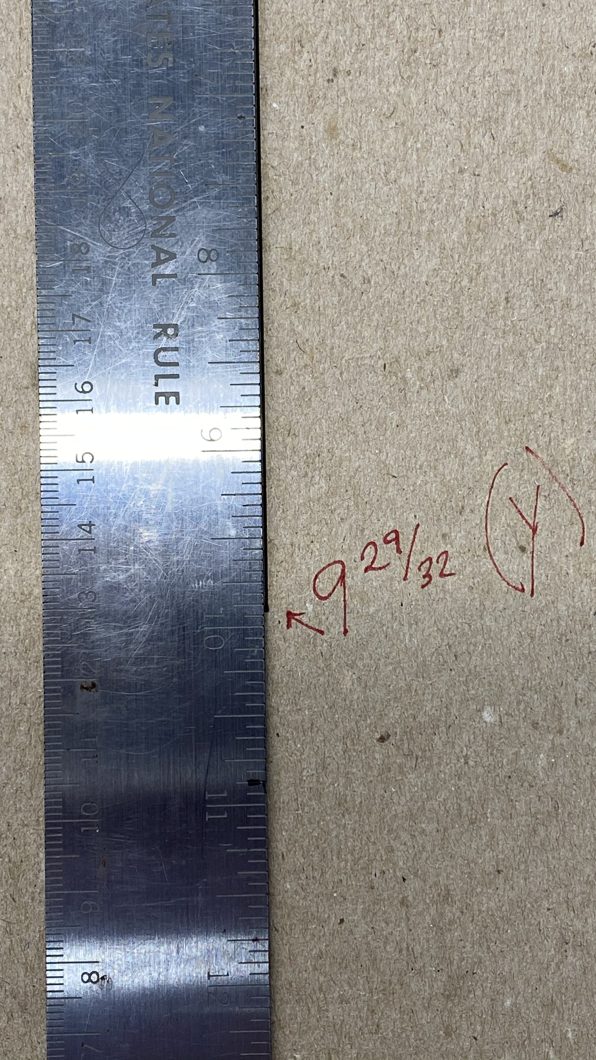
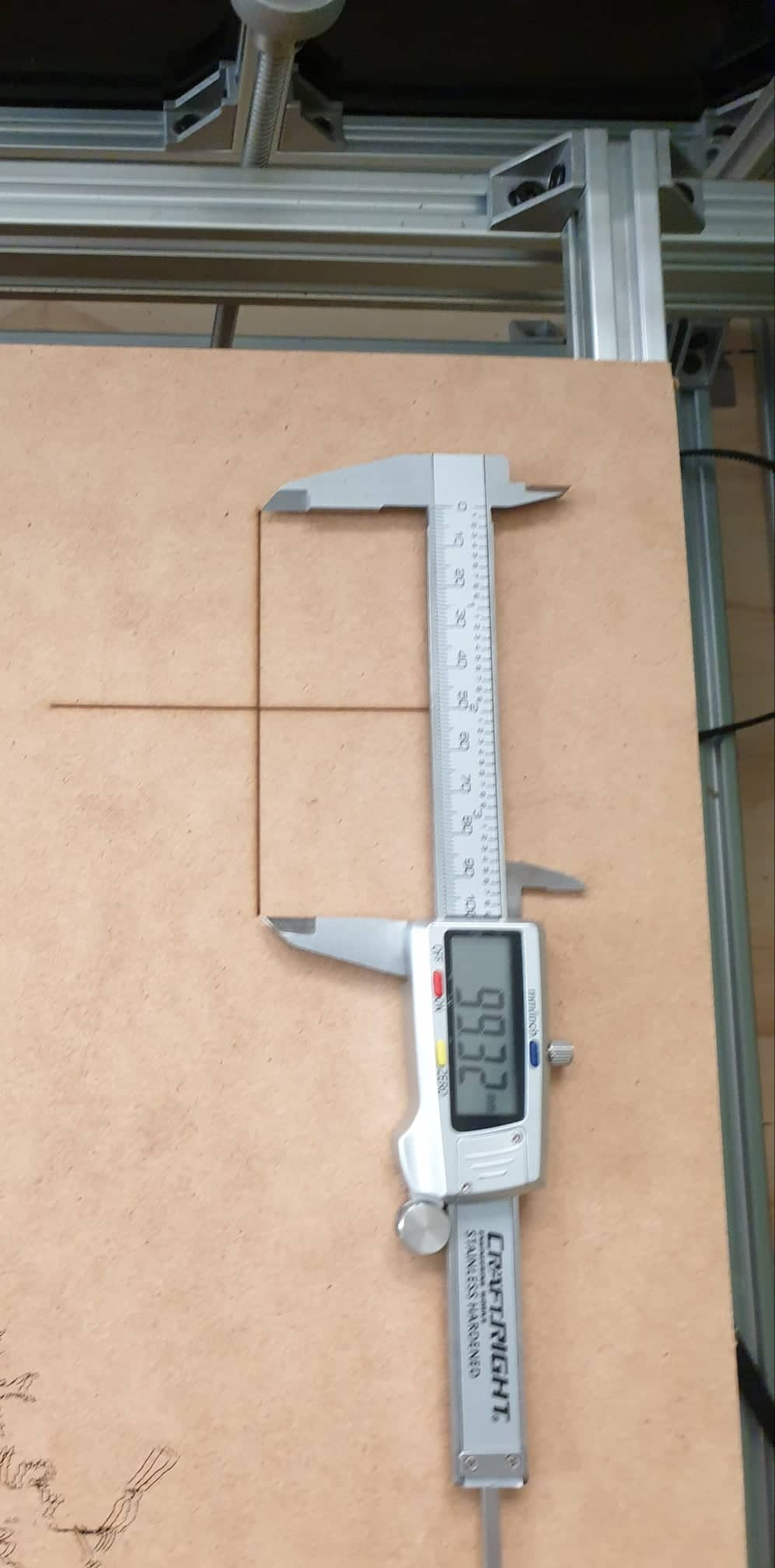
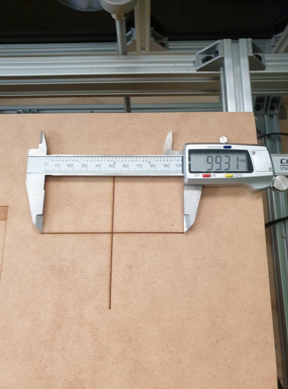
I was in a rush to lock up and get going but I did have time to run the cross test and came up with the following images, the mm moved matches my stepping fairly accurately (yes I used calipers  )
)
I know this is a little weird but my bed lays with its horizontal axis as the Y axis.
I still intend on running the paper test but I’m hoping this better explains the issue I am having.
Thanks again.
Looks like you are good on the skew, just one of your step lengths. But it’s easy enough to check them all at once, so no big deal. Happy hunting.
Hi @Stroonzo and @Dave01,
I have fixed my issue
The stepper driver dip switches were not set correctly.
I flicked a few more switches on and then ran the crosshair calibration test again.
She’s all set correctly and going back to the same position.
Regards,
Angus
That’s great! Glad to help. Those pesky DIP switches… 
This topic was automatically closed 30 days after the last reply. New replies are no longer allowed.