I found something that I wasn’t aware of over the last week and thought some of you might find it interesting.
My test of laser shape accuracy is to cut some shape and try to rotate it in place. This applies to gears and circles really well. I’ve been doing a lot of work to the machine and this test failed.
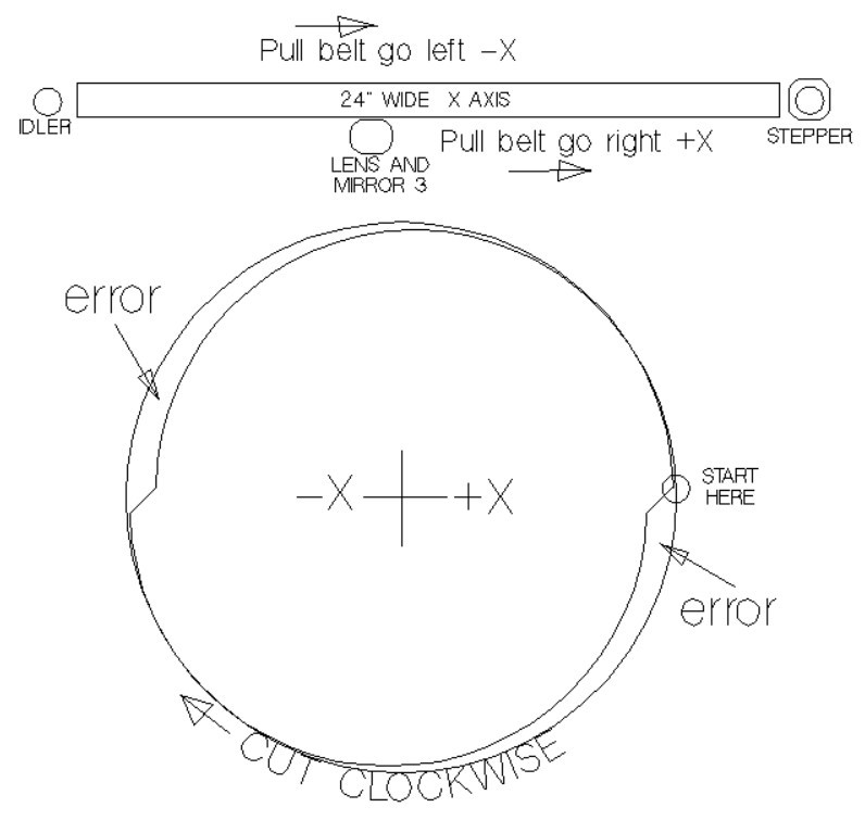
the attached image shows what I mean by fail. this is an 80mm circle placed in a perfect circle that was printed. I’m using the quality of a printed part to test the quality of the laser. On a clock face I’m finding that the cut part deviated from the printed gauge in the 3 to 6 o’clock and and 9 to 12 o’clock. the illustration shows a highly exaugurated error.
After trying a bunch of things I found the problem to be X axis belt tension. basically moving the X axis negative involves pulling on a belt that is three times longer then pulling on the X axis positively. when the belt has any slack in it, the change over from + to - causes a shift in the pattern. what is surprising is that the belt was tight when I saw this error but apparently not tight enough. Keep in mind that this error exists whenever the X axis changes direction. Solution is to keep belt tension very high or put a stepper on each end of the X-axis (which is way more complicated).
To make sure I understand, are you saying that the belt tension was causing backlash? I’m inferring that this is ostensibly from the space required for tooth engagement on either side of the motion. Am I getting this right?
I know some of this is unavoidable and inherent with a timing belt mechanism but is it possible that you have wear in the belt or that the tooth profiles of the belt and pulley don’t match perfectly?
No tooth backlash as the belt is wrapped 180 degrees around a 20 tooth pulley. This is more about belt sag thru the back of the 24” X axis. With axis change you can see the belt tension and sag slightly with direction change.
It might happen to the Y axis but it’s shorter and I can get more tension on Y due to my setup.
What was cool was to see the gap using a perfect circle. Nothing makes sense when you rotate it in the cut part because both have error.
Thanks for the links. It would be interesting to to get another take on this topic of circles that aren’t round. Russ’s two videos describe an unmeasurable problem with a pretty bizarre solution, to a non problem.
My problem is quite real. You cut a 80mm dia circle and then spin it in the cut. If you can then it’s round enough for me. At least my solution isn’t a redesign of my machine, but I’m also not makings a YouTube video either.
I also don’t agree with Russ’s theory that there is a flaw in timing belts. Or that all parts that have waves on them are coming from tooth pass frequency of the belt and pulley teeth. Something that often appears on the side walls of 3d printed parts. Another timing belt machine
Makes interesting videos I guess.
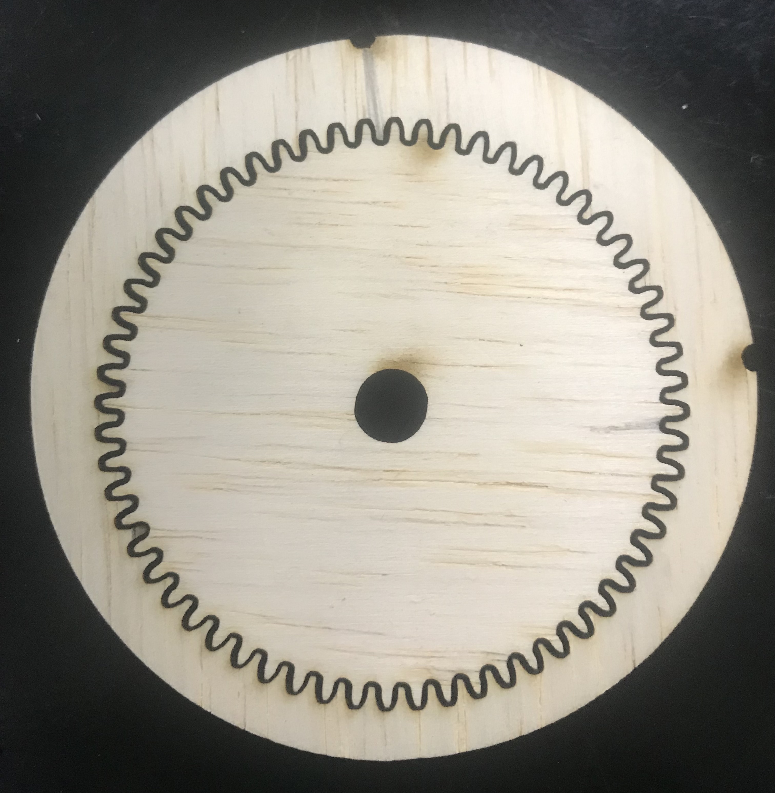
Updated on this issue. I found out the machine was out of square by 1.6%. Corrected that and the gear pattern rotates perfectly. I was kind of surprised that you can align all mirrors with it slightly out of square. The more you work with this machine the more you learn not to assume anything.
Attached is the gear pattern rotated 90 degrees, which is the worst case.