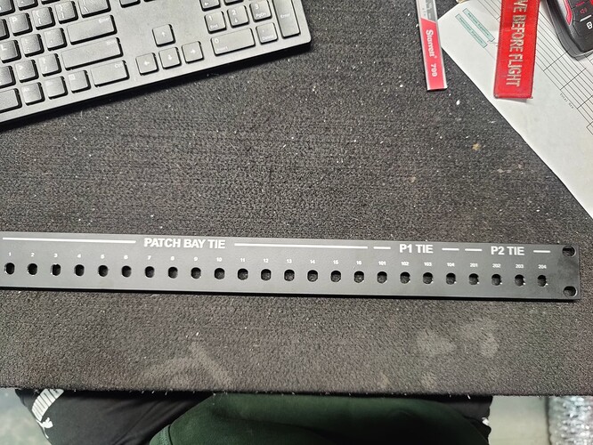
I am laser engraving labels onto panels and cutting out holes on my CNC router for connectors. What is happening is the labels line up with the hole on the right side of the panel but slowly move left as you look to the left on the panel. I believe this is a problem with the laser and not the router because when I measure from the cad file to real life, the measurement on the right side is perfect but on the left, it’s off about 1/16th of an inch and is noticeable. Its hard to tell in the pictures but the labels are off. Any help is appreciated, thanks
Jamie,
It does not look bad at all! Not like there is a chance to use wrong jack. I actually like the look.
But if you wish to perfect:
All CNC can and should be calibrated. Most (some) are good out of the box, but some are not so. Especially those with soft drive train like belts and rubber wheels. Most CNCs are screw driven and most lasers are belt driven.
My bet would be that screws are more precise than belts, but my laser and 3D printer (all GRBL based) are belt driven and both are 0.1mm accurate for whole length of the work area and never needed any adjustments from default, just saying.
If your CNC and laser are GRBL based - there are settings $100 and $101 for X:Y calibration, those usually are microsteps per mm (can be inches with specific settings). If you have different type of machine/controller - should have similar settings. You may tweak these values to calibrate dimensional accuracy of your machines.
I used to check it with regular caliper. Just extend it a little, drop it on the rail against hard stop at the end of rail, move gantry to touch depth probe and reset, then command to move known distance, like 10-30mm. I think it is trivial to figure out coefficient between commanded and measured distance. Measure and apply coefficients to each axis separately.
Above is assuming that in the artwork each label referenced to the center of the hole.
Is there a possibility that all numbers are typed in one line and not each reference to relevant hole? That can be font specific spacing.
To assure that it is actually difference in your machines and not in your code - try to back_plot both together. I really like this one: https://ncviewer.com/
Can you change the order of process? E.g. I would include hole 1 and hole 204 on a separate layer within my laser program, and first run the laser program so it only marks those 2 holes to a bottom sheet (or tape) on the laser bed. By aligning the previously router cut part with those marks, you can confirm the alignment and be perfectly confident in running the engraving job.
This topic was automatically closed 30 days after the last reply. New replies are no longer allowed.


