X- Limit Switch Keeps Failing

Hello, I’m hoping to get some direction or confirmation on what my next steps are for this issue. Background, this is a 60W ebay machine (similar to OM Tech) with about 500 hours “laser” time and many more hours “on” time. Controller is a Ruida 6442S-B.

I had the X- limit switch fail during homing. When checking the original switch I had no red LED when using metal or a magnet on top of the switch. I replaced the switch and a short section of wire to the cable chain by soldering and heat shrinking the wires. The replacement switch failed within a week and limited use with the red LED staying lit constant. Fortunately I had thought to purchase additional replacements. Thinking I had a bad switch I changed that one out for another one. These were different so I used a magnet stack on the x gantry head to trigger the sensor as they weren’t adjustable(stuck on with 3M to the aluminum)

This one failed the next day; however, the switch would appear to function via the LED, but would not show the limit trigger on the controller. When checking voltage the output would show about 10v with nothing triggering it and ~12v with something triggering the switch. I replaced this switch and saw the same failure the next day. I was concerned the magnet was the issue so I swapped that out with a bolt and nut through the gantry. I loosely installed the wiring for the last switch as the continuous soldering was getting old. Today again I have a failed switch on the X- limit with a similar failure but no 10V on the output. The LED triggers but no X- limit on the controller.

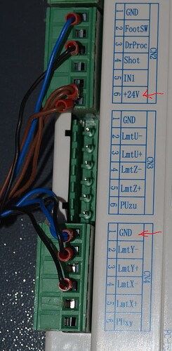
I have replaced it again and the wires back to the mainboard just in case there was a wiring issue. During diagnosis I temporarily swapped the Y- limit switch but that one has yet to fail. I do see on the Ruida manual that they should be wired with the Puxy which appears to be 5v, but the switches in the machine show 10-30v and are wired to 24v. They were, until I just redid the wiring this last time wired to the same 24v power and ground circuits.

I am fully expecting to have my wife call me at work again tomorrow and tell me she had to nail the e-stop because the switch failed again. I believe my next step if it fails again is to swap out the mainboard unless anyone has any other suggestions.

Thanks,
Dip
You’re probably doing it this way, but for the benefit of folks who may be new to this stuff

The switch output is an open-collector transistor, so you must measure it in-circuit with a pullup resistor to the power supply. You can do that while it’s wired to the controller (because the input pin has an internal pullup), but not with the output wire disconnected.

If you’re measuring the output in-circuit at the controller and it’s not switching, then it’s dead.

And, of course, when the controller isn’t seeing the switch change, then it’s really dead.

Always a good idea! :grin:

I regard Amazon / eBay as my parts locker, knowing randomly named sellers push junk bought from the QC reject bins of more reputable sources.

If you bought switches from a known-good source (which can be a reputable Amazon / eBay seller), then you may have recourse for a warranty issue.

If they came from, say, ERTAVM84Y, then you may have an entire batch of junk.

Although they’re not as fancy, you could replace the electronic switches with simple mechanical switches.

There may be an intermittent in the wiring, because the X axis wiring runs through the Y axis drag chain. There’s no way to test for intermittents, so I’d be tempted to replace the wire with a nice flexy silicone cable, maybe with a connector on the switch end. :grin:

Before you drop big money on a new controller, try another batch of switches from a different source and maybe replace that wiring.

I’ve used these quite a bit and have never had one fail… doesn’t mean they can’t but it does mean they seem pretty tough to environment and operationally.

I would think something is very wrong if you repeatably loose these for no reason…

At first I thought about drawing too much current from the controller, since that part hasn’t changed… but the switch is only conducting for a very brief period then opens again. So I think that kills that idea…

Have you changed where it gets it’s 24V?

On my machine, these are feed off the 24V tap on the Ruida CN2 and the ground on CN4.


Because of the way it operates, I’d tend to think supply voltage variations.

Have you ensured all of this stuff have a good common ground?


I’ll have to think on this… however you could go old school and just put mechanical switches in… if the frame is grounded you only need 1 wire… pretty simple and fool proof…

:smile_cat:

Thanks for this information. I was measuring in circuit only because it was easy to measure off my splices after cutting the heat shrink. I’m not well versed in transistors and complex circuits. Most of my electrical deep dives have been on 12DC for automotive.

Looking back on the seller for the 5 pack of switches just says generic so that may be part of my issue, as 3 of those have failed. The first one that failed was a single so I could get it next day. That one I got replaced through Amazon and the replacement is what’s currently in the machine with a full wire pull to the controller. Hoping for the best.

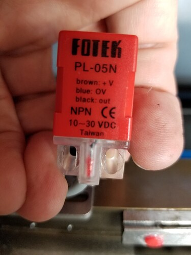
Of my switches were the PS-05N variant without the slot. As noted above maybe I got a bad batch.

The x- and y- switches were wired to the same power and ground off CN1/CN2. Since only the x- switch failed I’m skeptical there was an issue on those pins. The new one, with full new wire is wired to the CN4 Grd and the CN2 24V.

I do have some mechanical switches sitting around from a 3d printer project as I bought a 5 pack instead of just one. If the current switch fails I’ll probably fab something up to mount one of those until I can get a new batch of sensors(AKA it will stay like that until it’s no longer convenient).

Thanks for the responses, as of now it’s working with the new switch and wiring. Will update if there are any further developments.

Thanks,
Dip

Those are inductive sensors, not Hall effect sensors: they sense proximity to metal, not magnetic fields.

The original sensors may have been Hall sensors requiring a magnet, but the switches you have now operate differently.

The magnets are causing the failures by saturating the sensor’s ferrite core or magnetizing it enough to leave a magnetic bias. That field changes the core’s inductance, whereupon the oscillator and sensing circuitry no longer work.

Replace the magnets with a piece of sheet metal bent to suit, replace the switch with one that hasn’t been magnetized, and it (should) work fine forever more. Modulo the usual QC caveats, of course.

Take a look at the original switch on the Y axis, which may have the same problem straight from the factory. If it has the usual PS-05N or PL-05N markings or it (still) senses a nonmagnetic piece of steel, then you should preemptively replace it, too.

If I’d never made a mistake like that, I could be a whole lot snootier, but … hey, been right there, done like that. :person_shrugging:

This topic was automatically closed 30 days after the last reply. New replies are no longer allowed.