Xtool D1 Pro GCODE wrong

Hello together,
I have a problem with my new xTool D1 pro, burning a grid.
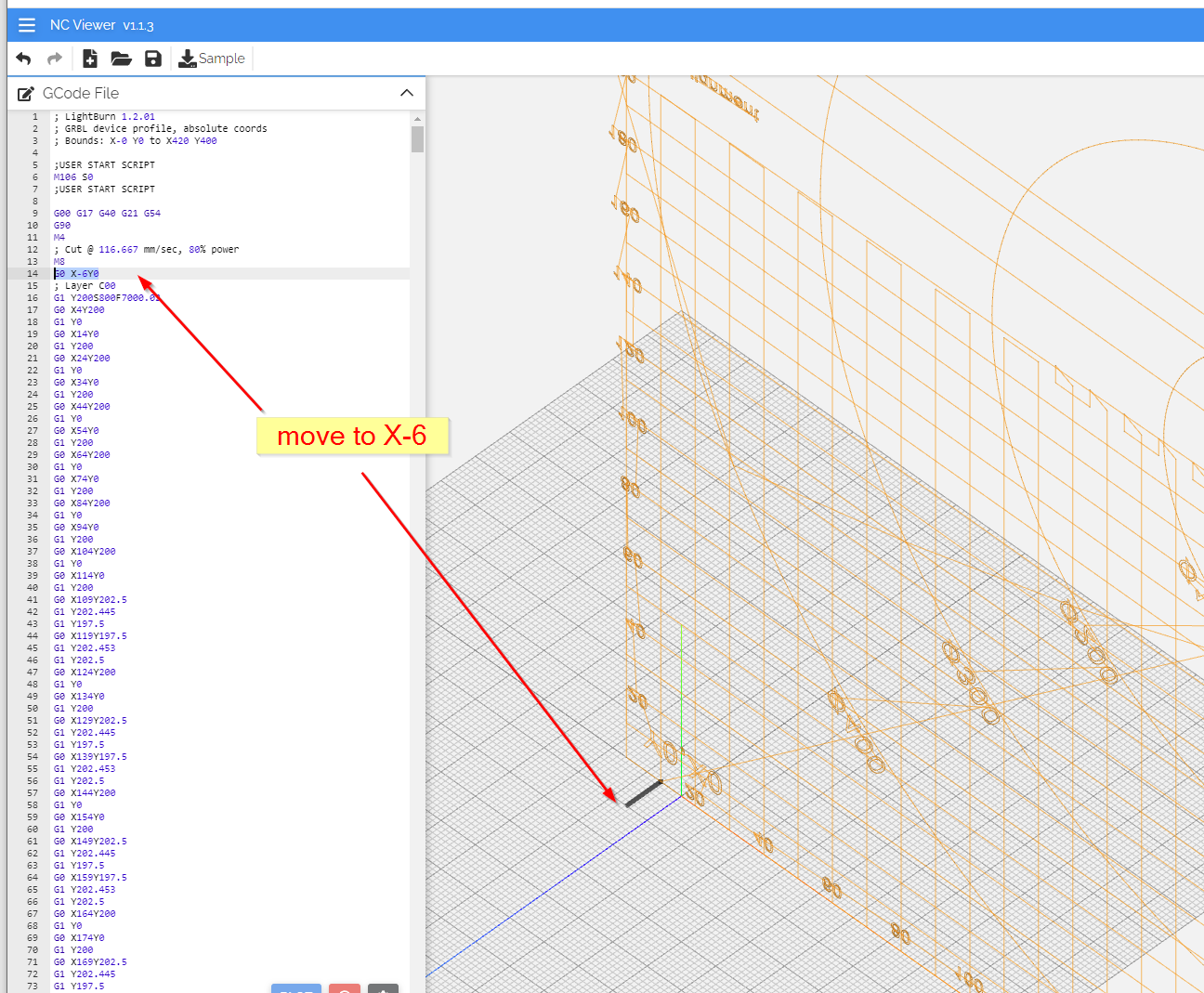
The grid in LightBurn looks good - but when I burn it, there is a crash moving the x-axis to -16 (minus 16). This is also shown in a gcode viewer (ncviewer.com)
LightBurn view:

But when I create a gcode file, than it shows some movements to the minus X axis!


later in the gcode file - there are moves to x-16

and this is the first X-axis crash.

This are the first lines of the GCODE:
; LightBurn 1.2.01
; GRBL device profile, absolute coords
; Bounds: X-0 Y0 to X420 Y400

;USER START SCRIPT
M106 S0
;USER START SCRIPT

G00 G17 G40 G21 G54
G90
M4
; Cut @ 116.667 mm/sec, 80% power
M8
G0 X-6Y0
; Layer C00
G1 Y200S800F7000.02
G0 X4Y200
G1 Y0
G0 X14Y0
G1 Y200
G0 X24Y200
G1 Y0
G0 X34Y0
G1 Y200
G0 X44Y200
G1 Y0
G0 X54Y0
G1 Y200
G0 X64Y200
G1 Y0
G0 X74Y0
G1 Y200
G0 X84Y200
G1 Y0
G0 X94Y0
G1 Y200
G0 X104Y200
G1 Y0
G0 X114Y0
G1 Y200
G0 X109Y202.5
G1 Y202.445
G1 Y197.5
G0 X119Y197.5
G1 Y202.453
G1 Y202.5
G0 X124Y200
G1 Y0
G0 X134Y0
G1 Y200
G0 X129Y202.5
G1 Y202.445
G1 Y197.5
G0 X139Y197.5
G1 Y202.453
G1 Y202.5
G0 X144Y200
G1 Y0
G0 X154Y0
G1 Y200
G0 X149Y202.5
G1 Y202.445
G1 Y197.5
G0 X159Y197.5
G1 Y202.453
G1 Y202.5
G0 X164Y200
G1 Y0
G0 X174Y0
G1 Y200
G0 X169Y202.5
G1 Y202.445
G1 Y197.5
G0 X179Y197.5
G1 Y202.453
G1 Y202.5
G0 X184Y200
G1 Y0
G0 X194Y10
G1 X-16
G0 X-16Y20
G1 X194
G0 X194Y30
G1 X-16
G0 X-16Y40
G1 X199
G0 X194Y50
G1 X-16
G0 X-16Y60
G1 X194
G0 X194Y70
G1 X-16
G0 X-16Y80
G1 X194
G0 X194Y90
G1 X-16
G0 X-15.999Y100
G1 X404
G0 X394Y200
G1 Y400
G0 X374Y400
G1 Y200
G0 X354Y200
G1 Y400
G0 X334Y400
G1 Y200
G0 X314Y200
G1 Y400

What can I do, that the GCODE is exported as shown in the LightBurn software?
Thanks

That’s odd. Can you upload the .lbrn file for review?

Hello,
because of copy rights, I reduced the content, but the failure still exists!
GridLBurn.lbrn2 (153.6 KB)
and this is the GCODE:
GridLBurn.gc.txt (113.6 KB)

I hope some one is able to support.
Thx

I think what’s happening is the negative X coordinates are there due to pointer offset configured for the D1. So in order to accommodate the -16 mm offset configured for the X axis the g-code has to go negative.

@berainlb - Thanks, but where can I change this offset?

This is defined in Edit->Device Settings.

It’s necessary for the functioning of your laser assuming you are using the crosshair pointer. If you do not use the crosshair then you can remove it.

The reason it’s configured is because the crosshair location is -16mm offset from the primary laser. So you frame with the crosshair but then need to shift for the actual laser operation.

@berainlb - Thanks, it works!

But when I use absolute coordinates, than this is not a good feature. Because with absolute coordinates I do not expect to have a pointer setting that is changing the coords.

If you don’t want to work this way then just disable the crosshairs and use the primary laser for framing.

Enable the “Enable laser fire button” and “Laser on when framing” in Edit->Device Settings. Then set the power level very low in Move window.

THANKS - but this I have done already in the past. But not changed the offset pointer.
Have a good weekend!

This topic was automatically closed 30 days after the last reply. New replies are no longer allowed.