XY offset according to camera/lens calibration

I calibrated my camera lenses and my camera today - man oh man, that took hours.

So this lens calibration tool was a real pain in the a… Anyway, now I have a nice rectangular image of my work surface.

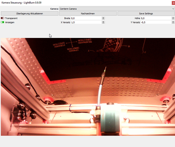
After the camera position setup I tried to burn a circle in the center of the setup document.

I noticed that I am +2.5 mm off in Y direction and - 2.5 mm off in X direction. When I use the XY adjustment of the camera, I move the preview image, but the point is still burned at the same (wrong) position.

What are the possibilities to set the offset for X and Y?

Camera Setting

{
“cameraIsFisheye”: true,
“cameraMatrix”: [
1081.1574626332188,
0,
0,
0,
1088.5160996440745,
0,
735.3727931633401,
717.9653929650426,
1
],
“distortionMatrix”: [
-0.13140629951485736,
0.772668772386548,
-4.119962867853075,
7.681688632182139
],
“inversePerspective”: [
-2.658744197819436,
-0.022171298368972525,
6.523776162839956e-05,
-0.01230115386318048,
-2.644804001900737,
-3.12344712654455e-05,
2727.630601441126,
1585.2134109591132,
1
],
“mapScale”: 0.8623647093772888
}

… oh and by the way, is there a way to flip the camera image?

I built the camera into the lid of my laser enclosure. When the lid is folded up for setup, it looks straight down and you can shoot a wonderful overlay image.

But when I close the lid, the image is upside down. A checkbox to turn the live image upside down would be nice.
It would, but it’s not currently possible because of the framework being used to access cameras on Windows. I’m in the process of writing a new one from scratch, and should have more flexibility for things like that when it’s done.

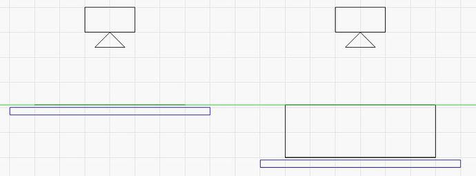
The image you’ve provided doesn’t show much of the laser, but it looks like you have a diode with a fixed-height bed - if you constantly change the focus point of the laser, you’ll need to re-do the camera alignment part for each different height. It’s meant for systems that have a movable Z bed, so the top of the material is always the same distance from the camera.

The good news is, the camera data can now be saved and loaded by right-clicking in the Camera Control window. If you use a few different material thicknesses, you can do an alignment at each height and export them, then import the profile for the correct height if you change material heights.

Yeah, you’re right, I have an Eleksmaker A3 with a diode laser. (with limit switches)

if you constantly change the focus point of the laser, you’ll need to re-do the
camera alignment part for each different height.

Okay, I don’t understand. If I align the camera vertically to the cutting table, what does the focus point of the laser have to do with the positioning?

It’s meant for systems that have a movable Z bed, so the top of the material is
always the same distance from the camera.

I would have thought that with such a system there would be more problems with the optical measurement than with one where the working area is always the same distance from the camera.

With a moving table I could rather imagine that a grid optically changes its edge lengths when you move it away from or towards the camera. This could cause the position X-100, Y-100 to no longer fit exactly.

But this does not answer my question - what is the function of the offset in the camera menu? As already mentioned, I can move the overlay image with it, but it has no influence on the axis position.

I would have thought that if I set an offset of Y+2.5 and X-2.5, these values would have a direct influence on the zero point of the machine.

So if I select a position X 150 and Y 150 for an object in Lightburn, it will automatically move to position X 147.5 and Y 152.5. But this is not the case.

Technically it’s not the focus point of the laser, but the distance from the work surface to the camera. As things move closer, they get bigger, and the calibration will be off more as that difference from the original distance increases.

To LightBurn, these two scenarios are exactly the same, because the distance between the top of the work and the camera is identical:

The offsets shift the position of the captured image in the edit window in LightBurn, so you align the camera image to match the work area, not the other way around.

1 Like

This topic was automatically closed 30 days after the last reply. New replies are no longer allowed.