Installed the extensions to my Atomstack A5 30W and the new wiring harness. Now Lightburn is displaying the working area vertically on the screen and the Y-axis is moving reverse of the printer so movement that should be going positive along the 800mm length it is displaying going negative off the edge of the displayed work area.
I have tried the old harness and new, deleted the engraver from Lightburn and re-added it. Tried different points of origin in Lightburn, but still no luck. The laser was working fine previously, and I confirmed the wires are correct, even swapped the connections on the board.
Thanks for the information. I’ll ask a series of followup questions/requests. Appreciate if you be very careful to address every question as thoroughly as you can or otherwise indicate you’re not sure about something.
Are you saying you don’t expect the work area to be vertical on the screen? The Y-axis is now about 2x what it used to be. This seems normal to me.
When you installed the extension, was there a pulley or something added that in effect changes the direction of the stepper direction? From pictures it looks like just a longer set of extrusions for the Y-axis.
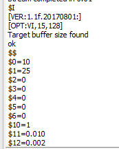
Did you make any GRBL configuration changes when you installed the extension?
Can you take a photo of the laser as it’s oriented from your perspective where the “front” of the laser is pointed towards you?
Also, confirm whether or not your laser has homing switches. If not, where is the laser head positioned when you start the machine?
Also, if you use jogging controls in Move window, do the controls work as expected? If not, in what way?
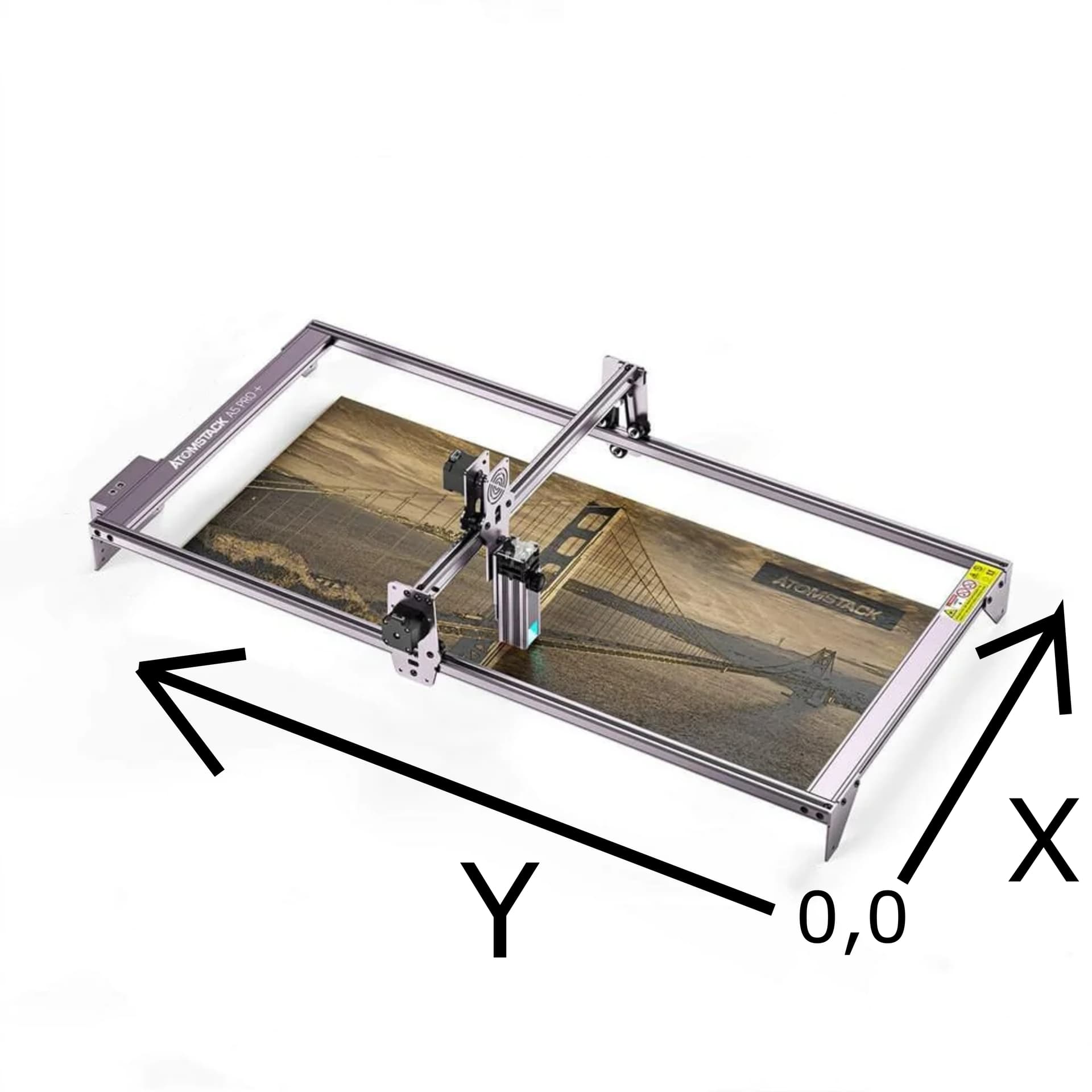
When originally installed the working area in lightburn displayed from left to right with the Y axis along the bottom of the screen. I am newer to laser engraving, but everything I can find I figure the moving gantry is considered the X-axis. I have been working with 0,0 as the lower left corner where the laser head is in the picture.
The engraver does NOT have limit switches ( a planned upgrade as the control board can support them). No other changes were made as the rails were just unscrewed and new ones slid between the rollers, new longer belts and wiring harness installed.
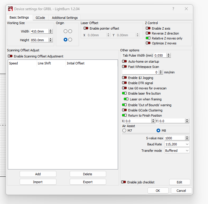
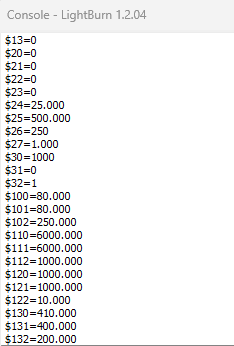
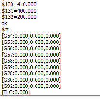
The only change I made was as I installed the printer in lightburn I updated the axis values, nothing in GRBL code.
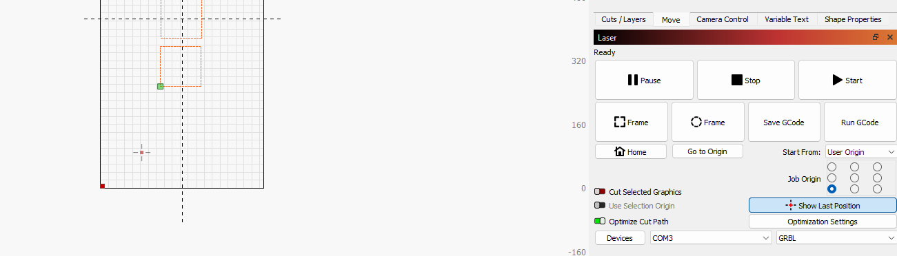
When I move UP arrown on the move buttons in Lightburn the head moves down, or toward what I would consider the 0 value and off the working area in Lightburn to a negative value. If I use the right and left they move opposite directions from the lightburn display.
Also, Lightburn is showing the Point of Origin on the lower left corner of the working area (red dot) but it should match the 0,0 location which should be the lower right corner. The blue dot on the Job Origin shows the bottom left corner of the 9 dots. Set to use User Origin which I have tried to keep at the lower right corner.
Using this picture as reference, if you push up jog button, does it go positive or negative X or Y. Can you explain for each direction?
Are you referring to the red square as point of origin? If so, that should match the Origin setting in Device Settings which it does.
I’m not following you on this. Your selection in Laser window is bottom-left and the square is also bottom left of your objects on screen.
Question, is your preference to treat your current “home” location as-is going forward? Or would you prefer to revert to more standard treatment of the X/Y directions and home location?
I had 0,0 backwards in my mind. Just looked at the old Y rail that has the markings on it and it is as you show.
Because my control board is the same location as in your pic
I found the GRBL command that allowed me to invert the movement correctly, from $3=0 to $3=3, so down moves down, right moves right etc. on the Lightburn screen to match the movement of the laser.
The orientation on the screen had me confused compared to the 9 dots when looking at the Job Origin, makes sense now. I think originally I had entered the X and Y values wrong in Lightburn which may have added to the false horizontal image before the upgrade.
If you’re satisfied with how it’s working then all good. I refrained from offering the $33 inversion as a fix because I didn’t think it should be necessary and that there was likely something else going on. But as long as you’re aware of what you’ve done and how it’s working then should be good.
I think the new harness has the wires reversed probably to the stepper motors, but I don’t have the pin tool to swap them, and they are all the same color, So it looks like the GRBL Code change is working. The big test will be powering it down, closing Lightburn and powering it on again and opening Lightburn to ensure it stays working. Thanks again for the help.