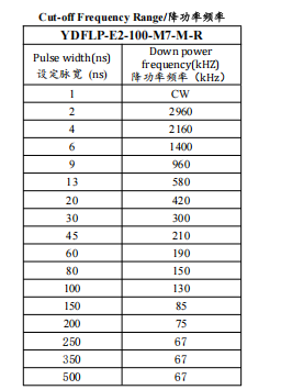
YDFLP-E2-100-M7-M-R Frequency Table

First time galvo user.

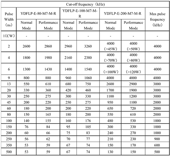
I can’t find a frequency table for the YDFLP-E2-100-M7 - I can find the E table, which is as below, and as I understand it the E is made with canadian/french parts and the E2 is just chinese copy parts which makes it cheaper but perform similarly.

If it’s the same, I assume for deep engraving, I need a high Q Pulse (200-500), how in general do I work out the frequency for settings like this?

Ie, if I start at Qpulse 500, and a frequency of 67, that’s the minimum frequency so I should go higher? Is there any rules on frequency use like this? If I go at a very fast speed, I will get less pulses per mm, which I assume means less heat which is less warping and therefore I need to balance speed and pulses to get higher resolution but not overdo it.

Is there an idiots guide to this?

In this context, the cut off frequency (67kHz) is the maximum frequency that will put out 100% power at the given q-pulse; frequencies higher than that, up to the maximum frequency (500 kHz in this case) will work but won’t see the same linear scaling behaviour from below 67kHz.

say at 30 ns pulse width, from 1-300kHz you will see power increasing linearly. from 300 - 3000kHz, you won’t see any higher total power being put out. So at 150 kHz you have “50w” of power. at 300 you have an output of “100w”. at 1200 you have “100w”.

thanks fins

So the “performance mode” is likely 100% power and “Normal mode” is probably 90% as there’s a 10% difference between all of the numbers.

With that in mind I presume there’s no point using it at 95% power on normal mode as that’s a further decrease in power. I should use 95% on performance mode?

Seems odd to add an extra frequency set. It just added additional confusion.

In short, the idiot guide is “follow the table and adjust your power in lightburn appropriately”

“Performance mode” must be activated through an RS232 DB9 serial port inside the machine. There’s PC software for it. It unlocks about 10% more power, but has a slightly more limited operating temp range. The software also has more diagnostic info about errors, warning, and temp stats.

You will need to take the side off the case to physically plug into that DB9.

There’s no “idiots guide”.

I’ve looked around a lot- there’s very little reliable info on how to operate them. I have an M7 300W and finding the best way to high quality engravings at high speeds is still confusing as hell.

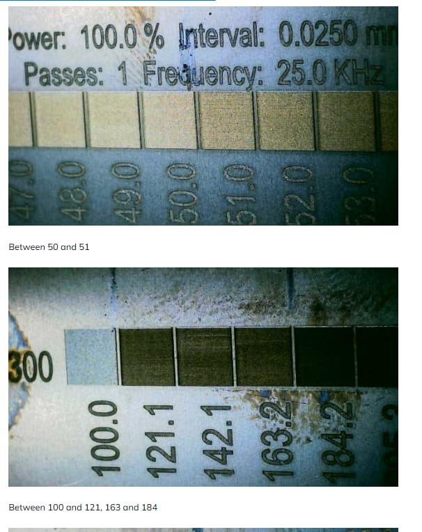
If you hit it too hard, a coin will heat up and warp. Also I look under a microscope and can see where it appears the metal spatters out of the cut only to solidify on the top edge of the line, making the engraving very rough.

I am confounded because, like, I get a hint of decent engraving at one point and want to compare with running slower. So I keep the q-pulse the same, keep 100% power and 0.02 LI, but slow speed from 5000mm/s to 1000mm/s and reduce the pulse freq to 1/5th. So it should be the same in terms of pulse energy and pulses per mm, it’s just being delivered slower.

But the engraving was MUCH shallower. I don’t see any reason why the pulses would be weaker when pulsed slower, both runs were below the cut-off freq so the profile of each pulse should be the same.

Now, if I were varying Power instead, I could easily write this off as nonlinearity , but that shouldn’t apply to Freq like I did.

This might be due to the reduced metal temp overall when getting pulsed slower.

Basically it feels like this is all about the ratio of material removal vs how much heat the pulse delivers to the metal substrate

Working on a coin is different than working on a thick bar of metal. The coin overheats much more easily, it will warp and warped material cannot stay in focus.

I could see the coin faintly glowing a dull red if I hit it too hard. But also, I could melt the surface of the metal without overheating the metal overall. This could produce a smooth surface but overall the graphics weren’t coming out well.

I’m still doing a lot of experimenting, I currently think the 60ns-80ns range may be the most effective for engraving. And I’m controlling the depth primarily by reducing the freq rather then Power.

I was working with the 2,4, 6, 9ns range that I could pulse up to 4000KHz by the manual. Overheating the coin was pretty often the result.

I do have examples were the taller features engraved one way, but the deeper looked radically different. This could be due to the focal point needing to be lowered, but the engraving probably wasn’t deep enough for that to matter. I think it was doing something totally different because the metal was at a higher temp on the later passes.

And it went both ways- some examples, the highest points seem to be melting into a shiny surface and actually had some good detail there, but the lower depths were a mess. Versus others where the higher points were muddy and it became shiny on lower parts.
1 Like

I have had a response back from JPT on the E2 and some of the down power settings are different to the E2, mostly lower than the E in the frequency range.

Hope this helps those who are using the E2s.

Hello, i have a JPT 100W YDFLP-E2-100-M7-M-R the Q-Pulse should go up to 500 but i can set it up to 5000 in Lightburn. Can that damage the Laser source if i set that higher than 500? Any ideas why it allows to go over 500 anyways?
Thanks
Martin

From my research, one any setting over a valid value it will clamp it to the max. My JPT source will go into a different mode that is essentially CW when the frequency exceeds the nominal max value. UV sources on the other hand can get damaged from improper parameters

Yes i hope that it will not exceed the max value becouse i am pretty sure i will one day make a typo and than there goes Q-Pulse 3500 instead of 350:) , but i wonder why lightburn let such numbers happen at all…maybe i did some setting wrong but i just cant see what that could be

The variations of possible q-pulse across brands of laser sources would be unknown to Lightburn Devs; there are certain limits that can be inferred from control boards, but , for example the bjjcz boards can handle co2, fiber and UV. Of the MOPA specific parts, a JCZ board doesn’t care about what’s at the other end of the connection.

It would be nice to have a standardized machine capability protocol, but I can’t see that happening anytime soon. Just hope both the laser sources and the control cards will deal with values that are out of range in a reasonable manner

So its a general issue not a wrong setting from me if i get your point right. So that should happen for many users i would think, but i couldnt find anything about that problem (if its a problem at all) what made me wonder.

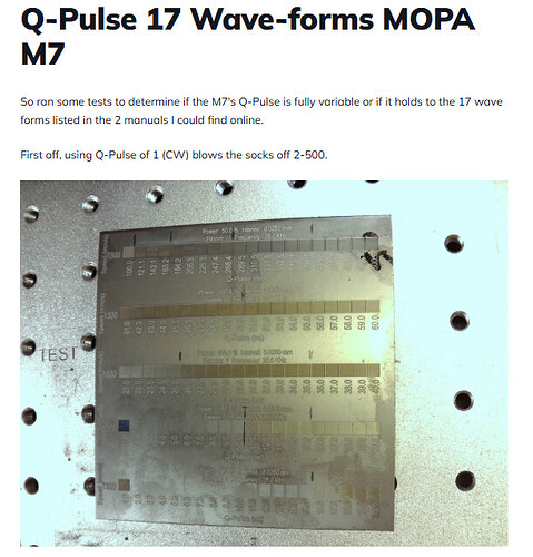
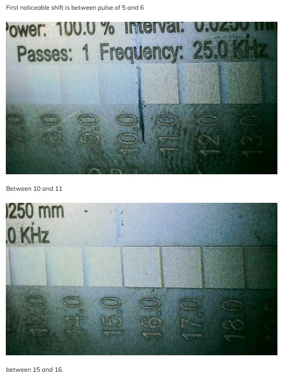
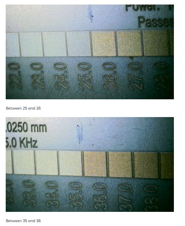
JPT MOPA will ONLY take one of the ~13 defined Q-pulse lengths. It is communicated digitally so it either matches or it doesn’t.

My JPT MOPA manual says if it doesn’t match, it changes it to the nearest valid type. I don’t know if that’s round-up, down, or where the crossover point is, doesn’t really matter. Use a valid pulse type for predictable behavior.

Note that each q-pulse type has a “cutoff-freq” and “max bandwidth”. In addition to “% power”

Assuming you specify 100% power, the power from each pulse is the same as long as you stay under the cutoff freq. So when you double the freq, the total avg power out doubles. You will max out the machine output for each q-pulse type at 100% power at the cutoff freq.

Above the cut-off, the machine will limit the power under the hood, the avg power output is basically constant. pulses get weaker but the freq does increase. afaik it shapes the individual pulse the same way as entering <100% power.

there is also a max bandwidth (max freq). I am pretty sure the source will protect itserlf but not sure how. Probably either skips the next pulse entirely until the min period counter resets, or reduces it to the max bw freq. Doesn’t matter as long as it doesn’t burn up from mistyping, because there’s no reason it want to use it near there.

I have not yet found any reason to go above the cut-off. The MOPA’s whole thing is the explosive power of its short pulses. More freq but lower power does not seem useful. If you need higher freq, go with a shorter q-pulse that covers your freq requirement within its cut-off rather than going with a longer pulse with its power throttled.

One NEAT trick is a q-pulse if 0 turns off the q-pulse, it opens the gate. The output is continuous, not pulsed. The % power does control the output. If you want to just heat something, this is probably what you want. Also if you want to heat without marking it you can raise the z to defocus it.

I want to try to soldering/desoldering with it. It could hit just the leads on a QFP, or it could heat the top of the device package without hot air until the solder melts.

1 Like

I’d really like it if LB let you enter your machine info, define valid q-pulse types and the cut-off of each. And a lot of the time I’d like to be able to say “100% of the cut-off, I just want max output, I don’t have a specific freq in mind”.

In rastering, you use the minimum focal spot size to determine your line interval, but also you want to fire pulses along the line at about the same rate. So speed/freq = line interval, more or less.

So I start with a line interval that doesn’t have gaps or overlap, specified a scan speed, then I have a freq requirement. I look to the chart for the longest q-pulse that still puts that freq below the cutoff if you want the most powerful output. If that’s too much, keep Power at 100% but go with a shorter q-pulse to throttle back. Because, again, the whole game of the MOPA is explosive power of a short-duty pulse. IMHO we generally want to throttle back with a shorter pulse at the highest power rather than the longer pulse at lower power to increase the explosive pulse power while keeping the average thermal heating as low as it can be.

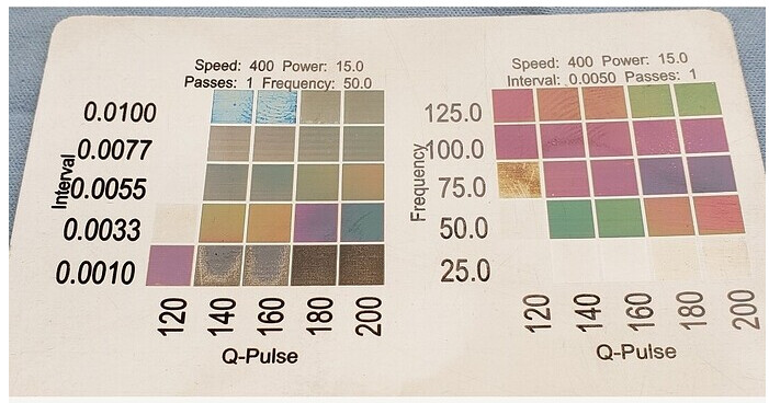
I’m still a bit unclear on the science of getting colors on stainless, though. I can get colors but not necessarily the fastest, deepest settings. And it’s so weird that there’s an area where color shifts in a continuous spectrum as power increases, then it just burns, but then sometimes I find isolated one-off colors- like green at a specific LI/power/q-pulse/freq/speed, but no other colors adjacent to it on a settings grid. Weird.

I’ve confirmed this with testing on my 60W, it does go to the nearest valid pulse.

my main concern was that i can damage the laser source by accidently type say 5000 instead 500 for the q pulse and the whole thing blow up (i checked again and i can set it up to 10000) .It seems it wont, as the source is smart enough not to go over its max specs. well hopefully.

So i wonder now if everyone can set his Q puls value so much over the 500 as i can or its just a problem of my setup?

The trick with q pulse 1 to go CW might get really handy for some soldering to get heat very precise on a tiny spot, good idea.

Rounding up?


How do you know?

:smiley_cat:

Easy to test, do a material test on SS in the color ranges with q pulse variable from 100 to 200 You will see duplicates above and below the listed q pulses. I did 100 squares on titanium, posted it here a while back.

I posted this over on LMA a while back. A few mistakes but the test is still solid.


1 Like

Well, let’s talk about what we’ve been learning. I have a 300W so I have higher power available, and it can cause problems.

My observations:
Most of what a MOPA “cut” is is due to the explosive shock of a powerful pulse. Reducing Power was always counterproductive as far as I could see.

The MOPA’s explosive power does not work on a hot metal or ceramic surface. You can have the whole metal piece getting red, or just overlapping raster lines on a small graphic, the surface alone is still hot. Not only does it stop throwing sparks when it overheats, it (stainless) can easily melt and flow into the channel you’re cutting, which collapses. But, I have actually made use of this smooth out a pitted area too.

You do need a really good microscope to understand what’s going on. Some of the engraving I did with longer Q-pulses actually blasted a deep hole where it hit- like, really deep and narrow. It didn’t look like that without high magnification.

I thought it would be like sanding- best way to get a smooth deep engraving would be to start with “rough” passes of large pulses widely spaced, then work down to smaller, finer pulses to polish. This often didn’t work as planned because the pitting features (or “lines” from a large LI) tends to “capture” the beam and channel it into the pit. The light polishing passes could fail to do that because they’d channel into the pits and deepen those instead of polishing down the crests.

A key factor is the ratio of how much cut you’re doing vs how much heat you’re delivering to the substrate.

My current understanding is that first you figure out the spot size- generally I’m seeing this as the size of damage the laser does, rather than the laser’s focal diameter itself, but they’re pretty close.

Then you set LI to be 0.5-1.0 of the spot size, AND then make the pulse spacing the same number: freq=speed/LI. So you basically fire pulses in a square pattern and avoid excessive overlap. From there you can see the max q-pulse you can give it from the chart, but that could easily be too much (with my 300W at least)- “too much” generally being you see the substrate melt. I usually go with a shorter q-pulse but reducing speed and freq together is also good.

The condition of the surface can radically change how it reacts to the beam. I melted part of the coin by overheating, I stopped it but I saw it had actually created a mirror finish. I got the settings back down and tried again but you could clearly see the green line of the laser lost most of its intensity when it passed over the mirror-polished zone. It was reflecting.

I have been looking for interesting things to do with CW (q-pulse=1). I figured this would be the best for coloring stainless because it shouldn’t actually engrave out a piece of metal, but it tends to heat and warp the sheet without getting a color change. This is actually a riddle I’m trying figure out- the color seems to hinge on pulses being able to create surface heat and get the color change on a single pass. It actually won’t work consistently if it relies on the prior raster line to still be hot, because the time since the last pass varies by graphic width. It wouldn’t be very useful to have the color vary by width of the raster.

CW might be useful for doing PCB reflow and rework. You could put the outline of a BGA device into LB, defocus it a bit, and CW would be the best choice since no pulsing damage. Just scan over and over to heat the device until it lifts. You don’t have to worry about plastic headers next to the target like you do with hot air.

I’ve got a theory that color change can be a lot faster and more consistent if you do a prep pass first. I haven’t gotten consistent success yet though. It seems to have the capacity to work better though.

1 Like