Hi Oz,
I understand the issue with the zero point. I assume that with JCZ cards you’re getting step feedback, so you always know where the motor is. But wouldn’t it be more straightforward to implement a software zero that maps to the current real position (as you mentioned), whether the controller provides that position or not?
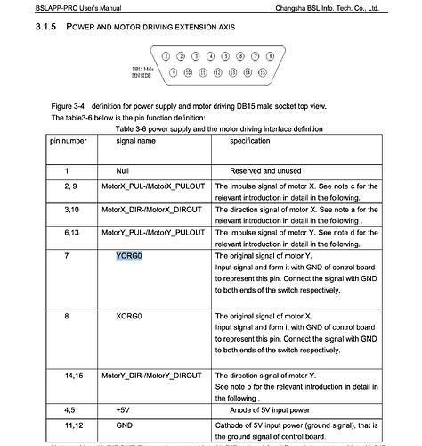
From my perspective, using a controller-based zero (like the actual hardware origin) is fine, but I don’t really see a major downside in using a software-defined zero instead. It would remove the need to “rewind” the motor just to reach hardware zero again. JCZ likely uses this for the XORG pin, which sets zero via hardware - but I imagine that pin could also be read and interpreted in software?
A consistent software-zero approach might actually be easier for you to maintain across different boards.
As for Z movement per pass… that would be fantastic. But please keep in mind that many users still buy EZCAD3-based boards only for Z-axis control. In almost every enclosed laser system, a motorized Z-axis is essential, because the manual focus crank is usually difficult to reach and in automated setups, it’s non-negotiable.
Here’s how I would prioritize Z-axis support features:
1.	Input field for part height -> auto Z-focus
2.	Zeroing via hardware pin (for homing)
3.	Z-height per layer for engraving at different levels
4.	Axis-to-motor mapping
5.	Z-height per pass
Motor-to-axis mapping would open up a lot of powerful use cases: XY tables, switching between rotary and Z-axis when only one physical output is available, etc.
For the UI, a dedicated “Z” tab could make sense, or alternatively, Z-controls could appear under the Laser tab when enabled.
We almost exclusively sell enclosed systems - open systems are rarely feasible in Germany due to regulations. That’s why we’re still forced to offer EZCAD3 to customers… and honestly, I’m ashamed to even suggest it…
Please Oz free us from EZCAD3. 
If we can help let me know !
