Z Axis Stepper Calibration

I’ve upgraded to stepper motor control of z axis to allow bed height control from Lightburn. I am now able to rise and lower the bed from the controller (RDC6445G-EC), however I can’t calibrate steps to match actual travel. I got the bed to move through trial and error at step length of 1.77. Then I measured actual travel vs displayed travel and used the “calculate steps” function on the controller to get actual step length (.067240). Problem is, the bed won’t budge (motor stalls/ squeals) at this setting. I have tried adjusting controller displayed speeds from their default (380/10/10) down to 5 with no result. I also tried adjusting the driver voltage upwards with the dip switches, and changing the Pulse/Rev dip switches. Not sure what to try next.

Settings:
Step length 1.77
max speed 380
jump off speed 10
start speed of key 10
Changing the step to even 1.8 or 1.7 yields stalled motor, as do adjustments to speed

Parts:
DM556 Microstep Driver (dips set to 4.3A Peak and 400 Pulse/Rev)
Leadshine 2 Phase Stepper Motor 57HS22
Ruida Controller RDC6445G-EC

I used this excellent tutorial from MW Laser, however step length is different for each machine so it is of no further help. Z Axis Upgrade on Red & Black Co2 Laser with Ruida Controller - YouTube
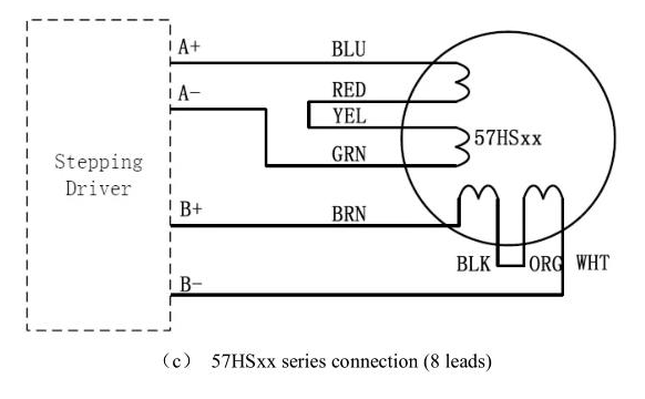
Make sure it is wired to the driver like this:

LeadShine 57HS22 wiring

Verify the connections with an ohmmeter, because the color codes may have been garbled. With the motor unplugged from the driver, the resistances of the half-windings (blu-red / yel-grn / brn-blk / org-wht) should all be equal. The resistance from A+ to A- should equal the resistance from B+ to B- and both of those should be twice the half-winding resistance.

If the colors are right and the resistances aren’t, then the color code is wrong. DO NOT PROCEED; report back and maybe we can figure what happened.

The 400 step/rev setting is too aggressive. The Z axis driver on my laser is set to 10000 (yes, ten thousand) step/rev, which may be absurdly high, but at least it works.

That gives a 0.39999 µm/step length, which won’t match yours, but gives you some idea of the teeny step size to expect when you recompute it. In round numbers, 0.4 µm is the wavelength of deep violet light.

With all that in order, give it a go. The platform won’t move very fast, but the motor should turn: everything afterward is a matter of fine tuning.

Great info thanks. Yes I did use that diagram to connect the motor to driver but I did not double check with a ohmmeter first. I will snip the wires, test, and report back. I would have guessed that if the wires were crossed, the motor would not work at all? It does move, it just moves too far/fast.

As for the step/rev, I thought 400 was the least aggressive. Should I try double that, 800? Available settings range from 400 to 25600. After I change the pulse/rev, is trial and error the only way to find a corresponding step length that will move the table?

Thanks for your help I am new to stepper motor programming.

That’s the usual outcome, but if one half-winding is reversed it will behave poorly. Given that you observed “motor stalls/ squeals”, it’s worthwhile to verify the absolute basics.

It works the other way: a smaller step size (more steps/rev) requires less torque to move the platform during each step. Think of it as pulling a car up a hill with a comealong: it’s easier to move it one inch per click than one foot per click.

No. Set it to 10 k, because that’s what the good folks at OMTech seem to think is appropriate. Which is why I recommended it.

The step length is not a free variable. It is exactly determined by the leadscrew pitch and the pulley tooth ratios.

Measure the distance between threads on the leadscrew. Mine has a single-start thread with 10 threads in 40 mm, so the thread pitch is 4 mm.

Count the number of teeth around the motor drive pulley and a leadscrew pulley. Both have 15 teeth in my OMtech.

Then calculate:

mm/step = (pitch / step/rev) × (motor teeth / leadscrew teeth)

400 µm/step = (4 mm / 10 k) × (15 / 15)

Which, now that I work it out, does not agree with the 0.399 µm/step shown on the LightBurn Vendor Settings screen. It’s off by a tidy factor of 1000, which shows my KT332N controller uses millimeters, not the microns used in other Ruida controllers:

400 µm = 0.400 mm

Verily, a foolish consistency is the hobgoblin of small minds.

Bonus: trust, but verify.

So calculate the mm/step for your hardware and enter it in the Vendor Settings for the Z (or U, depending on the controller) axis, with attention to the units. The 6445 doc says it uses microns, so you’d use 400, rather than my 0.400.

Then set all the speeds to 4 mm/s and all the accelerations to 50 mm/s².

The KT332N requires a reset / power cycle to put some of those values into effect. I have not been able to get consistent results without a reset, so I think the firmware recomputes some internal values, but not all of them.

With all that lined up, see what happens …

2 Likes

You nailed it friend- grateful for your expertise. With pulse/rev set to 10k, pulleys both 24 tooth, leadscrew pitch of 4, step length result .400. With your recommended adjustments to speed and acceleration, the bed moves smoothly and quietly, as well as the expected distance! Now to fish that autofocus pen wire through the drag chain…

1 Like

Bonus!

Glad to be of assistance …

1 Like

This topic was automatically closed 30 days after the last reply. New replies are no longer allowed.