Z-axis with my OMTech Polar and lack of power

Well, life happens and you never know when it’s going to barrel at you full steam. So, I’m circling back to this question again because I wasn’t able to respond to my other post before it was closed due to “Life” happening. :wink:

I want to thank Jack Wilborn for his reply and link to that post - it did help, some. But it’s still a very confusing thing, trying to understand which Z-axis setting is for what exactly. But I was getting better at it. And then…

I found a YouTube video from Edmonds Workshop about adding the Cloudray Ruida 6442S Control Panel to my Polar. Game changer! I did the ramp test - multiple times - and now I simply use the Z-axis control on the 6442S to lower it to the setting I want and away I go! HOWEVER…

Ever since I received my Polar it struggles to cut anything. Whether I use the OMTech formula to set the height according to the formula within Lightburn or manually focus with the controller, I have to set the power and speed well outside that of everything I can find out on the webs. I ran my ramp test multiple times because of this cutting issue, but every test the point in the line that is perfect is right around 13-14mm, and if I use that height it takes far too many passes to cut through.

I have a 10-watt diode laser also. On some woods it struggles, but I can get a clean cut within 6 passes on the hardest 1/8" ply. I work with a lot of Birch ply, but I have a Basswood ply that my diode cuts in a single pass, like butter it’s so soft. But my Polar struggles with that same lumber.

The Polar engraves really well at the correct setting according to everyone else - 150mm/s @ 21% +/- power depending on the wood. But the average cut at 10mm/s @ 26% +/- power and it’ll surpass 5 passes on 1/8" Birch or Basswood before it starts to cut through in spots.

Yes, I have turned the potentiometer on the back all the way to the right, even backed off a smidge just to see if the full turn caused an issue, but no change. And turning left on the knob lowers the power, as expected. I have cleaned the mirrors and lens with a glasses cleaning cloth and 99% alcohol. I took things apart to check for damage. I’ve watched the Ammeter and it’s spot on for power settings, not low or high.

Right now I have to set my cuts to 10mm/s @ 40% power (5-6 mA) at a height of 10.6mm to get through my 1/8" Birch and Basswood in around 3 passes, but they aren’t clean cuts with a lot of fibrous connections and plenty of burn.

So, is there anything else I should look at? Could it be the lens supplied by OMTech? I am planning on upgrading the lens to the Photonics OMTech Polar Magnetic Lens and Tube kit simply because my large, oafish fingers have a helluva time pulling the lens out for cleaning, but I imagine there are differences with lenses?

Again, any insight and wisdom is greatly appreciated. The more I learn, the better I get and the more I’m able to help others with their lasers in my local community. And a lot of that knowledge comes from you, here. So, thank you, all! I’m really good with diodes now, but this Polar and C02 laser has been a bit of an adjustment. And I really would like to resolve this cutting issue because I see others use their Polars and they have no struggles at all. So again, thanks for your help!
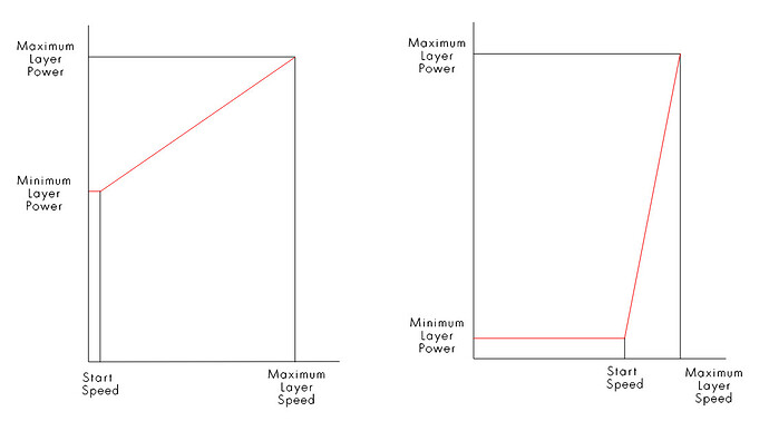
Are you aware of the start speed controller setting and how it relates to min/max settings?

If you run the machine at or below the start speed it will lase at low power only. You speed is set to 10mm/s and most Ruida seem to be at 20mm/s. This would allow only minimum power settings. You can check it via Edit → Machine Settings… Mine is 5… :crazy_face:

I don’t have one of these so I’m unaware of this potentiometer function or wiring.


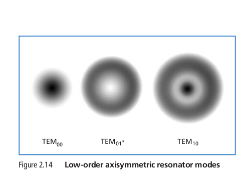
When you have issues like yours, I’d suggest an alignment check starting at the tubes output to check it’s TEM mode or resonance.

It must resonate in TEM00 mode…

Screenshot from 2022-03-16 06-40-55

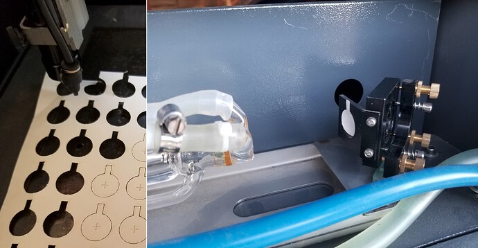
I do mine like this… I cut out targets from watercolor paper…

:smile_cat:

Thanks, Jack!

You are correct - my START SPEED is set to 10mm/s. So setting it to 5mm/s won’t cause any other issues?

The Potentiometer is actually called the BEAM ATTENUATOR on the machine. Which is a fancy name for a potentiometer that increases or decreases the lasers output power on the Polar. But, unless the wiring is incorrect internally it isn’t the culprit.

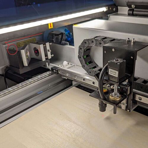
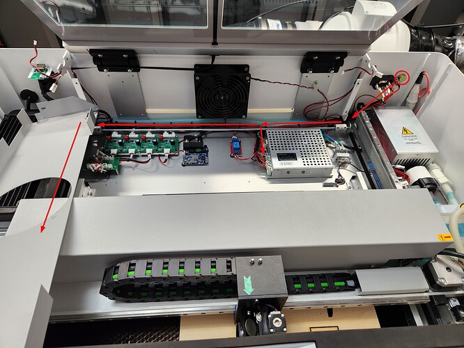
So, doing the TEM test would be tricky on the Polar as, like the Glowforge, the tube sits atop the laser gantry, and as such, the end of the tube sits inside this enclosure that looks tricky to take apart. I can’t get a good photo right now without tearing it apart, but here’s a pic that SORT OF shows it. It sits behind the mirrors in this image (that have been added to create a red dot output for centering and framing). I drew some arrows to show the top of the enclosure and the internal mirror alignments inside. Hopefully that makes sense.

Anyway, I finally got fed up with receiving one email per work day from OMTech asking me to do things I already replied that I’d tried, so I sent them some audio and pics of outputs to show how poorly it’s working then called them and asked they actually call me back, which they finally did 4 days later. Once I was able to explain over the phone (because they didn’t seem to be reading my email replies) what the machine was and wasn’t doing and everything I had done to prove it was hardware and not software or other basic things covered in the manual, they agreed it was likely the power supply or the laser tube. They were going to send a new power supply, but then another tech listened to the audio I’d sent of the machine “Warbling” when on and said that’s the sound of a failing tube, so a tube is set to arrive next week. If that doesn’t work, then it’s got to be the power supply.

Below is a photo of a test I did. The TEST on the left is done using the “17mm - material thickness in mm = Z-offset distance in mm” formula, but using 10mm/s and 26% power. The TEST on the right is using the same offset distance from material, the same power (because that’s the power you’re supposed to be able to use to engrave wood), and the speed of 150mm/s, which is the speed you’re supposed to be able to engrave wood with. You can see the difference. And this is that super soft Basswood that my diode laser cuts like butter - if I’d have used any other wood the test on the right would be blank because it isn’t producing enough power to do much of anything. The box around the test on the right is using 10mm/s and 40% power to try and cut it out. After 3 passes it had a depth of 0.92mm. If I’d have used the 21% power at that same speed like I’m supposed to be able to do, again, nothing would have happened.

So, that’s where it stands now. I’m going to take the weekend and take things apart to prepare for the tube replacement next week so I’m ready when it arrives. Fingers crossed that’s actually the culprit, because I’ve owned this thing since the end of July and still haven’t been able to use it, which is truly testing the impatient, instant gratification part of my psyche! :grin:

I’ll try to remember to update as to the resolution, or lack thereof, when I have one.

Thanks again for your plethora of wisdom! That TEMS test is something I never would have come across if it weren’t for your insights!

No, mine is set to 5. It delivers minimum power at 5mm/s and starts to ramp it up when it increases speed… This is a user configuration value…

Don’t know how this is wired or to what. My Ruida does not have an external knob. The Ruida control tube current via software, so no external tube current adjustment should be needed.


I can see the issue from the photo graph. Can you negotiate a piece of tape in there…? I know it’s cramped…

Might be more easily done to check the tube, if it fails, no need to mess with the lps and the converse is probably true.


Did you start a new thread?

:smile_cat:

The START SPEED being set to 10 might explain why when I tried grayscale anything under a certain light color wouldn’t engrave at all. Or it just could be whatever is wrong with the tube.

Yeah, I have no idea why OMTech decided to add the attenuator. It seems very silly since you have to turn it to full power once you unbox the machine and are setting it up. Makes no sense to me.

This is a new thread from the previous regarding Z-axis’s, yes. Because life got in the way for a while and I didn’t get to reply within the 30-day window. But it’s more of an extension of that thread since adding the Cloudray controller removed the need for me to do the software Z-settings. But I’m still having issues regarding much of the same. Or thought so until this week.

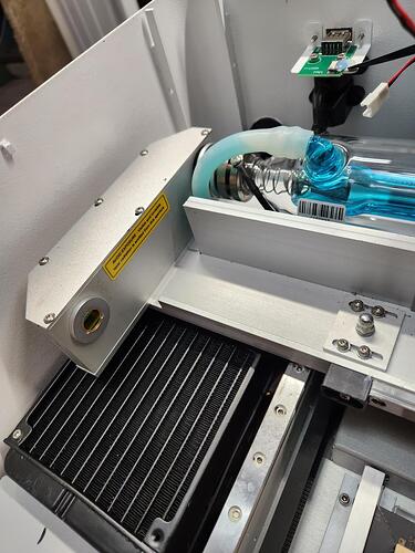
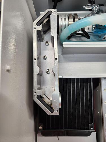
So, what am I supposed to do with the tape? I have the enclosure opened now; here are some photos of it closed and open. Where would you like me to place the tape and what to do after? And I did clean these interior mirrors, but they weren’t dirty and it made no difference.

Thanks!


Can we (I) see a photo of this?

This is concerning to me, with a Ruida there is absolutely no need and is a poor implementation of a Ruida installation if it’s doing what I think it is.

Are you electrically competent, could you see how the Ruida L-PWM1 output is wired to H or IN of the lps?

:smile_cat:

Okay. Sorry for the delay, but I had a lot of work to do to trace wiring. There are a lot of components to the OMTech Polar, and adding 2 individual rotary inputs for the included two rotary units made it even more cumbersome.

Firstly, here is a photo of the Attenuator. It is on the back above the security key plug and next to the power switch and cord.

On the inside of the unit there are 3 wires coming off the back of the attenuator.

From there it is wired along the inside back of the unit behind and below a couple covers. This image show the direction the wires take.

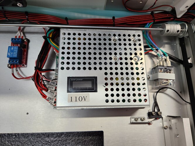
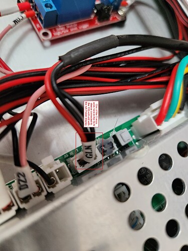
One wire connects to the 110-volt unit with the milliamp display in it that allows you to see mA power usage at whatever percentage of power you’re currently using the laser at.

It connects to the GL(i)N connector of this unit, but because of the identifier sleeve I can’t tell which it actually connects to.

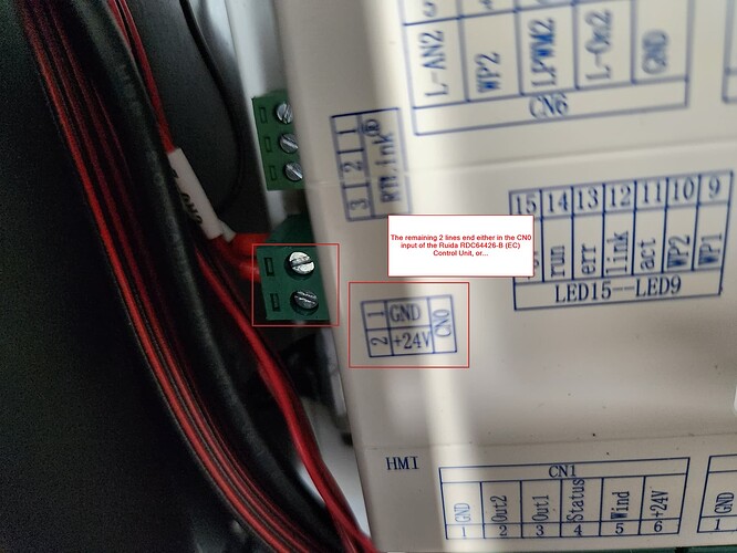
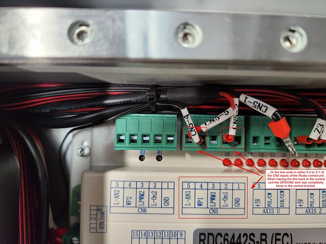
The remaining two wires follow the back then turn under the water coolers radiator to the Ruida RDC6442S-B (EC) controller and connects to either CN0…

…or to the CN5 connections in the L-ANI and WPI connectors or the L-ON1 and GROUND connectors. I don’t know which yet because I have to completely pull out the cooler to trace the wires all the to the Ruida controller. As you can see from the photo, the wire that is supposed to be in the GND connection is loose because as I tried to trace it out and ran my finger across that line it was completely loose in that socket, so I have to take out the controller to be able to reattach it. There were several improperly seated connections as I traced different lines across the different chipsets. Since I haven’t been able to use the laser I hadn’t gotten around to using the rotary’s, but if I had they wouldn’t have worked because connections weren’t seated on those boards.

As to the L-PWM1, as you can see in CN5, there are no leads connected to that connection at all. So it doesn’t seem to be connected to anything. I’m assuming by “LPS” you meant the Laser Power Supply? If so, it’s an entirely enclosed unit (as shown below the image of the backside/interior shot of the attenuator), so I would have to perform a lot more tear down to see what connects to what within it. IF you meant something else, please clarify.

With all this information, do you have any other thoughts or things I should try? The replacement laser arrived today, but I want to get all your ideas out of the way before I install it. But before anything, I need to pull up the Ruida so I can properly reconnect that wire.

Thanks, Jack!

DOH! Okay, there are 2 power supplies. The one below the actuator and the one with the mA display. Durf. I get it now. And apparently that answers your question as to the IN and L-PWM1 connections. The other PSU seems to be specifically for the water cooler, air- assist, and the exhaust fan.

Sorry for my momentary stupidity! :smile:

Interesting. So, once I properly reconnected the loose ground wire and put the laser back together it actually produces enough power at the OMTech suggested speed and power settings for engraving and cutting for the Polar to etch wood it wouldn’t even mar before. It’s still not producing remotely the power it should be, but it’s improved to the point that it etched Birch, which it couldn’t do prior.

I did a Material Test card after putting everything back together. As you can see from the linked video, it did lightly etch, but as usual came nowhere close to cutting through the 3mm ply. The row it is working on is etching in percentages of power. It starts at 0% then goes up to 70% power (which is shown as 100% on the materials card). As you can see the only etching it did was at the 70% power box, but if you watch the mA display you can see it doesn’t even try to do anything until it gets to that last section, and even then it’s 01 to 04 mA max. And yes, I set the machine settings start power to 5, just like you suggested, and that Layer is set to Image and is 0% power at the lowest and 70% at the highest power.

Does this give you any new ideas? If not, as soon as I can get some replacement PC/CPU coolant (since you can’t get the OMTech coolant anymore), I’ll be swapping out the tube, which arrived 2 days ago.

As always, thank you for your help and wisdom!

I keep coming back to this thread… it has me wondering what the beam attenuator is actually doing.

A pot is usually just a voltage divider. It being wired to 24V (same as the controller) is unusual.

The IN of the lps can be either a pwm signal or a dc control voltage. The LAN1 is actually a dc control voltage output that is essentially the same as using it with pwm… Whatever voltage is present between 0 and 5V sets the output current limit.

I suspect this is the label for the connector that is Ground, L(on) and (i)N of the lps. Which goes where…

Can you chase it more definitively with an ohm meter?


How about some paper between the end of the tube and the housing? You don’t need tape, just hold it still…

:smile_cat:

So, the 2 wires from the potentiometer run back to the Ruida controllers CN5 set of inputs into the L-On1 and the L-AN1 connectors (and the Ground). There are so many little control boards and tangles of wires that it’s boggling to try and grasp it all. I asked OMTech support for a schematic, but the manufacturing side of the business refuses to share it.

But some good news. And some interesting news as well. First the good:

This thing is too heavy for me to move around by myself, and although OMTech has decided they would willingly replace the unit with a new one, I have been trying to avoid that. Mostly because the only friend I had under 65 and mostly ailment-free who could help has moved away and the only other option I have left is setting up a whole system of ropes and pulleys from the rafters, and that seems like a recipe for disaster. Living in what’s basically a coastal retirement town does have its drawbacks. :smile: So, I asked them to send me a replacement laser tube instead and we’d try a few things before I caved entirely and asked for the replacement, and they agreed that was fine. They sent the new laser tube, but then there was a fiasco with zero slack in the existing coolant system tubing and their gluing the tubing to the intake and outtake barbs of the original laser tube, so I had to track down the silicone tube size and order more, then siphoning out the coolant, which was harder than it should have been after discovering they not only had tie-downs across the internal coolant reservoir, but the reservoir itself is also glued down to the chassis. Anyway, I finally got the laser tube replaced and I went from 4-6 mA at 70% power to 16-18 mA at the same settings.

They had sent me a link to the power output I SHOULD be getting, which is 21-26 mA on a 50-watt output C02 laser, so I told the tech I had been corresponding with that the power was still low but much improved, and he told me that’s exactly what I should be getting. His answer is at odds with what their documentation states, and then I recalled a thread in the Lightburn forums here that you were corresponding in where you talked about laser tube length and the actual wattage based on tube size formula (which I can’t find now that I want to link it), and it occurred to me that their claimed 50-watts might be a fiction based on his claim that 16-18 mA was exactly correct, which indicates it’s probably closer to a mid-40 watt output based on what I remember reading in that thread I can’t find. Which was interesting.

So, I start testing the lasers output on the same material it would barely engrave before, but each consecutive material test card is showing less and less resolution and is getting a lighter and lighter output. And I still can’t cut through it despite the temporary increase in laser power. Plus, the systems “Warble” that had mostly gone away after replacing the original laser tube with this new one and only seemed to be coming from one of the coolant system radiator fans was increasingly getting louder and louder and seeming to come from the entire machine again as it had done from the moment it arrived. I also noticed that the new laser tube has a little line of foamy bubbles across the top of the tube again, even though coolant is flowing and I tested the water flow diagnostic with my external Ruida controller.

So, I asked the OMTech rep if they would send me both a new power supply and a new coolant system pump. They finally arrived this week, and I do not mind telling you that replacing certain things in this all-in-one system are a nightmare! Everything is so cram packed together, there’s almost no room for tools or for big fingers to do delicate work. I even almost gave up entirely trying to remove the old power supply, because even though I had removed all the screws holding it to the chassis I still couldn’t move it until I discovered it was also adhered to the chassis with a thick thermal paste, something I was NOT expecting and no one at OMTech warned me about. Thankfully it eventually parted, and I was able to use a razor blade to remove the paste from the bottom of the old PS and apply it to the bottom of the new one, because I was going to lose my sh!te if there had been yet another unexpected delay while I hunted down and purchased even MORE parts that should have automatically come as part of the replacement parts kits.

And NOW - and hopefully permanently - everything is working as expected! Aside from the 16-18 mA thing, but again, I’m going to chalk that down to deceptive marketing. Though I’m still testing. Thankfully power has not degraded since the replacement of the power supply, and the foam bubble line has dissipated from within the laser tube.

There’s probably over a hundred yards of cabling inside this thing if you were to lay it all from end-to-end in individual wires. And things are put in odd places. Half the coolant system is on one side of the inside of the machine and the remainder on the complete opposite side. Same with electronics. Looking over it all for so long I can’t see any reason why you wouldn’t pair systems together instead or running parts to and fro and back over themselves again. Both internal sides where the guts are stored are of equal size and there’s no obvious reason to have designed it to be so cumbersome to repair. But at least I’m very aware of how it all works on the inside now, so future troubleshooting, should it be needed, will be easier to do. :smile:

Anyway, I’ve got some ramp tests to run now with the original mirrors, and again after, since I’m replacing the lens with the new American Photonics OMTech Polar / Gweike Cloud Magnetic Lens Kit! I guess it doesn’t matter whether you purchase an all-in-one laser or not, there’s always upgrades to be had!

Thanks so much for all the help, Mr. Wilborn! You are a glorious font of knowledge and I wouldn’t ever hesitate to seek your help again in the future! You keep me learnin’ and I deeply respect that.

I don’t follow this… L-On1 is the laser enable. It goes low (active) to cause it to lase. The L-AN1 is the analog output, compared to the LPWM1 which is the pwm control… Either can be used to set the IN voltage of the lps.

Not sure what they are doing here. My only thought is they are using it to compress the 0 to 5V control voltage to the IN terminal…

Let me clarify this… They are a dictatorship/communist country. If you haven’t yet noticed, western countries are not doing well dealing with the Chinese government in general.

We could probably boost our production rates if the people are ok with a 12 hour day/6 day work week.

This was relayed to me from a Chinese immigrant about 15 years ago… Anything they know is considered to be state secrets, giving state secrets away is considered a crime, which could mean prison…

So, limit your expectations. Doesn’t hurt to ask, but limit your expectations.

What they do have a lot of is B :poop:

I don’t know of a formula, although I’m sure there is one as what limits this is the physics of amplify part of the laser mechanism. The 50W tube they sole me in my OMTech China Blue was 880mm end to end length…

Mine was maxed out at about 44W at around 16mA.

Since you have a console, I’d suggest a mA meter … if you’re paying attention you can see anomalies of operation quicker.

Do you have the ability to check the optic for cleanliness and check it’s alignment?

Don’t know what to tell you about the noises you are hearing…

The coolant is between the gas tube and the next tube. Little bubbles aren’t an issue, but a bubble of any size attached to the inner tube where the heat is generated can cause overheating in a small area and crack the glass.

This is a <30 second video when I put glycol into it for winter.

Ran this way over a year with no issues… It thickened up the coolant and dropped my flow rate by 50%.

This shows you what the controller is reading from it’s inputs.

Mine actually failed on this input. I didn’t use the door protection, so I moved it to the input… If I try to run it without the chiller, it says door protect in the Ruida display… I know it’s the chiller.

Mine has a line of led’s that show the inputs. Mine showed inactive on the leds but the console showed active.

Do they supply the coolant? I ran distilled water for about 8 months and then OMTech had their antifreeze type coolant. Been running it ever since.

Good luck

:smile_cat:

I have no idea what I’m looking for as far as how it’s supposed to be wired for power. The way they designed it seems silly to me and there’s so much cabling all stuffed together in these tight little rows it’s incredibly difficult to trace out anything. Unless there’s something I’m not understanding, I would have put all the cooling and air assist on one end and the electronics on the other to simplify wiring. But what do I know?

As to the schematic, this is where I get lost. I used to think Orion Motor Tech was a Chinese company, but then I learned they were a U.S. and India based company who imported and sold K40’s (and other things) and weren’t involved in anything but distribution. But then they diversified and created the offshoot OMTech that deals solely with lasers, some still imported, but I was under the impression the Polar was sourced and built in the U.S. But I’ve read so many conflicting reports I have no idea what is right or wrong. I believe they source their tech support from either China or India based on the middle of the night responses and the one sentence replies, but when I finally got someone on the phone to help, they were out of California. But you could very much be correct about the schematics part given they won’t share. But not much I can about that, I guess.

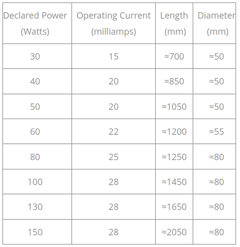
The OMTech’s Polar 350 laser tube is 35-inches / 889mm long. They claim it’s 50-watt, but my outputs aren’t the same as their troubleshooting guide says they should be for the 50-watt lasers, so I asked for clarification and am waiting for a response. But if you look back to my response from the 12th you can see it comes with a mA meter in the video, built into the machine. It doesn’t seem to track output well, though, as you can see from the video, really only showing the start and ending aM measurements across what is an entire row of differing power. I have been wondering if that’s normal or not. If not, I guess that’s the next part I ask for.

Noises aren’t so much a worry as they don’t seem to corelate with the issue directly, so I am less worried about those unless they prove to be tied to what’s going on.

The Polar came with the OMTech coolant installed. That’s why I tried so hard to salvage it, because OMTech was out of coolant for months. When they got some in they did send me extra, and I purchased an additional gallon of it as soon as they told me they had a small batch available, so I’m set there. Coolant formulas are so vast and differing that I didn’t want to just up and try one only to find out it hurt my machine. Even from the different OMTech support reps I’ve dealt with I got different formulas to put in their machines since they didn’t have available coolant at the time, which I took as a very bad sign. I’d think that if you’re selling a particular brand that all support would suggest the same thing, which would make me feel better about the company understanding the needs of their own products. But since they didn’t, I just wanted to keep what it came with. I’m glad I was able to siphon out and reuse the coolant because I was stressing about what formula would be best otherwise. :smile:

And thanks for that spreadsheet of power vs length. That’s what I was talking about from the other thread that I had read but couldn’t find. But now I know where to find it from now on! :wink:

Oh - I also tested the laser to make sure it was still centered after swapping out the tube, and it’s not. Now it’s slightly to the right and further forward. But I have no idea how to align it since all the mirrors are housed in that box with no fixtures attached to them for movement in any direction, so I am awaiting a response from OMTech on how I’m supposed to be able to align them. I had a K40 for a short while and spent weeks trying to align those stupid mirrors and keep them that way, so I’m hoping it’s an easier process with the Polar. I wish the cursed things would simply auto align! Maybe someone will develop an auto-alignment kit for the Polar one day so I can make that my next upgrade! :grin:

It’s always simple to use distilled water. It will freeze, is a problem, but its’ one of the best for a coolant. De-ionized water is supposedly the best, but it’s acidic and turn into distilled water if it gets exposed to oxygen/atmosphere… Distilled is lowest cost… I used it for almost a year.

If it’s too conductive, the anode voltage has been known to jump to the coolant and make everything it touches at the anode potential or high voltage.

The less conductivity (dielectric constant) the better for lasers.

It’s clearly not a 50W tube… another misleading item from them… :face_with_spiral_eyes:

Don’t have one, so can’t make much of a suggestion about cleaning and alignment on these…

Good luck

:smile_cat:

This topic was automatically closed 30 days after the last reply. New replies are no longer allowed.