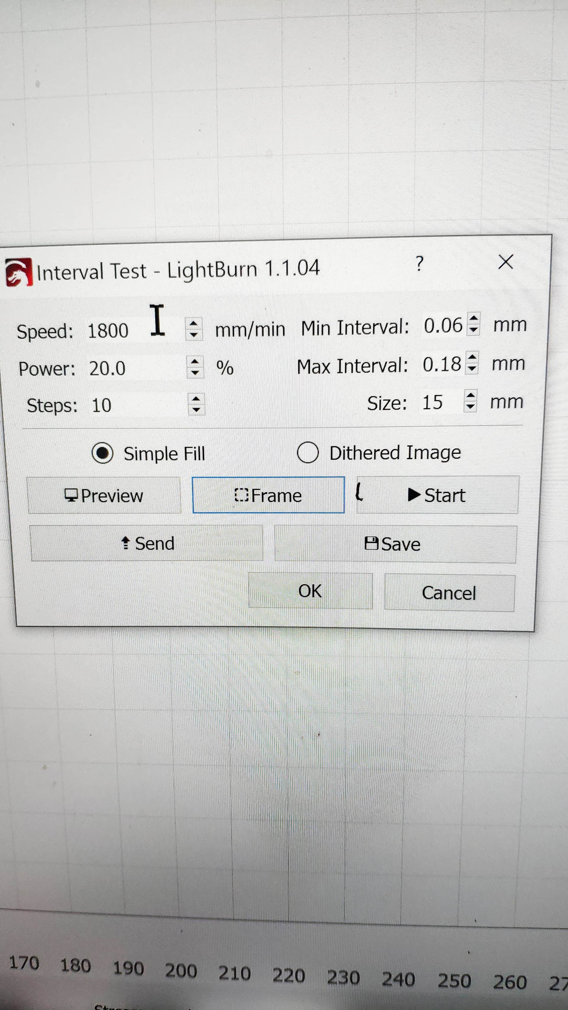
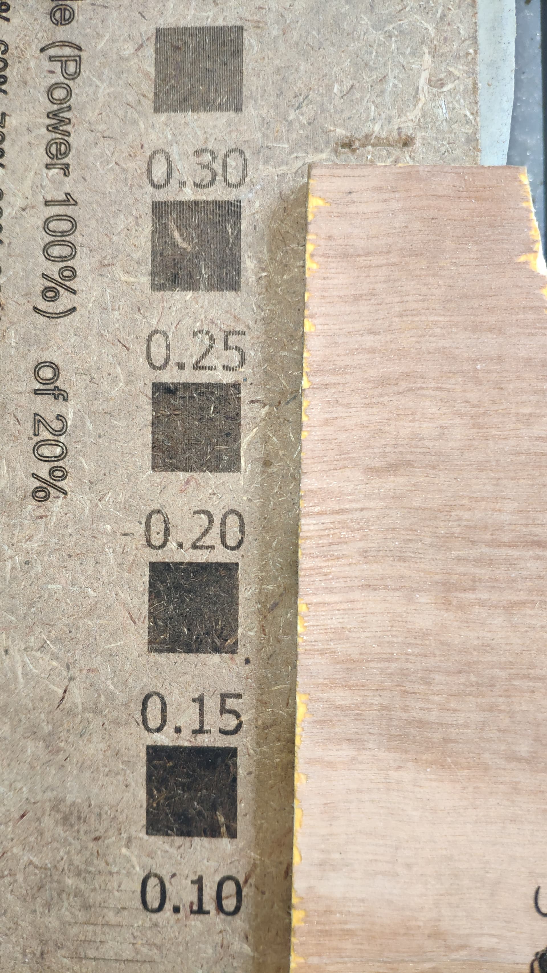
you appear to be comparing the settings for my power/speed test with your interval test, should they be the same? These are the settings (power set at15 but speed constant 1800mm/min) I used for the interval test.
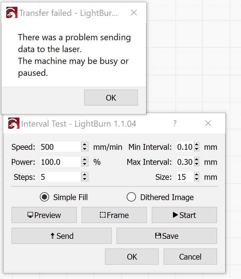
now it wont play ball at all, even jog doesnt work. Tried to do interval test and I get a “cant send to laser maybe busy or paused”. I’ve hit the reset button on the machine control board but that doesnt sort it. Turned it off and on of course and removed and replaced the power, closed and re-opened lightburn too. No idea why it thinks its busy but how do I get past this if reset and power out/off cycle doesnt do it?
Sorry to be asking such stupidly basic questions lol but I was hoping reset would… well, reset
@merlyn ran a series of powerscale tests. His first test was at 100%. The later tests were at lower power levels so he could get sense of finer scale controls within a narrower range of values.
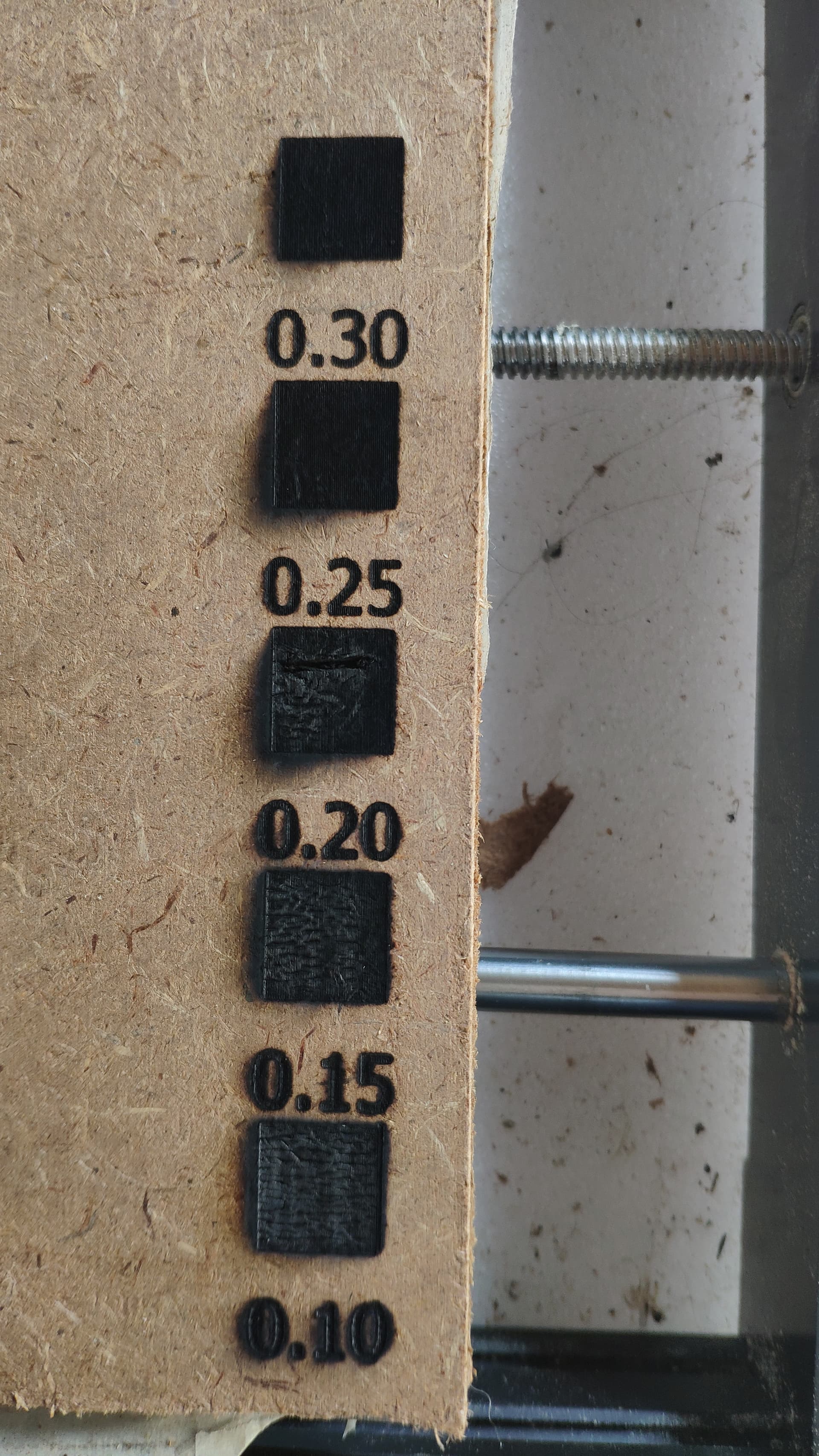
I don’t know who you are replying to here. If it was me I was just pointing out that the interval test results you posted were not definitive because it looked like the highest interval still had overlap.
Make sure you’re set to the right port in Laser window. Try rebooting your computer.
That was to jkwilborn as his were labeled interval 0.1-0.3
COMM PORT THANK YOU I can at least talk to it again ![]() no idea how it changed but it had taken itself off comm port 4 where the machine is to comm port 1 where it isnt and unsupprisingly it couldnt find it.
no idea how it changed but it had taken itself off comm port 4 where the machine is to comm port 1 where it isnt and unsupprisingly it couldnt find it.
Go back to ideal power for the material. You don’t want burning to influence the perceived line width.
Hard to tell from the photo. If you have a microscope or a loupe try to get a good look. You may want to run another interval test between .15 and .20 to optimize this as the jump seems pretty large in this case. But you’re looking to have no overlap while at the same time minimizing any perceived gap. Better to have slight overlap than slight gap.
perfect thank you exactly the info I needed. I have a loop and even a usb microscope so ‘I’ll look in to it’ if you’ll forgive the pun ![]()
Just seems to me that there is something incredibly wrong to go from nothing at 3.5% to burnt at 8.5%. The laser is 20 watt mine was 30, but it still required about 80% power to get a good burn…
The (last) image show 30% of 15% or 0.06 times the lasers, maybe, 5 watts says it’s doing this at 300mW.?
The original delta change is from 175mW (3.5%) to 475mW (8.5%) now your zeroing in the 300mW area?
If that seems OK, then I retract my issue… this, someway, seems wrong… ![]()
![]()
Yes I think that seem to be a large part of what I’m finding its nothing to charcoal everything is in a very small percentage change low in the supposed power scale but I’m such a noob that I didnt know if thats meant to happen. I was expecting, naively, to be using 0-50% power maybe for photo’s and 90% for cutting but I seem to be at 2-8%$ for photos and by 15% its burnt. The material is a darkish brown so that will help it absorb the energy…
You need to check the pwm control and see if it’s has the range that’s expected. You have some kind of hardware issue from the looks of things.
Don’t remember if you have a voltmeter, didn’t see anything in the thread…
![]()
I have a meter but no clue about pwm. if i remember correctly its a 3 wire connection to the laser head from the MB… it’s a long time since I had to ask this but… what do I stick where and what do I expect ![]()
You are only interested in the ground and pwm connections.
Most of these have a pwm signal that is 0 to 5v. At 50% power you will read the rms value of the peaks or 2.5v. You can check it with 100% or any other power levels.
If this is working then it points to a failure of the led module itself not following the pwm control.
When you do this, it’s very important not to cross any of the pins with any others. The connectors a pretty small so be extremely careful. You don’t want to break something that is working.
I usually make up some female pins with a short wire to allow me to push it over the pins in the connector.
Good luck
![]()
I tend to think this is not the case although I initially thought the same. @merlyn is getting power modulation as evidenced in the various test burns.
I suspect the material being engraved is extremely sensitive and only allows for a very narrow range of useful power levels. The way the interval test behaves seems to back this up as the material looks to scorch or darken more broadly very easily.
Tests on other materials would reveal if there was a genuine issue with power modulation.
Voltage test is still worthwhile. Just wouldn’t jump to the conclusion that the laser module is necessarily faulty if PWM voltage turns out to be correct without a broader set of tests on other material.
there are three wires from the board to the laser, Red, Black and Yellow. I am assuming the yellow is PWM, Red power, Black ground. Ground to PWM (Black to yellow) is 11.75v whether the laser is on or not.
Power to ground (red black) only has voltage when the laser is firing (I use the ‘fire’ button in lightburn so it wasnt stupid power while I was in there with a meter.
I have tiny needle points I can use with the meter so I just slid them in to the back end of the connector with out opening it so all still plugged in and working.
If this is constant 11.75V then this is likely power., not PWM. You should make sure that this is the expected wiring. Did the laser module come with the machine or these were assembled separately?
Do you have markings on the laser module and controller to verify pin purpose?
This is likely the PWM. Try firing the laser at different power levels. It should scale from 0-5V proportionately with power.
ERRUGH, the red/yellow possibility occurred to me later. sorry, I have medical condition of chronic fatigue, amongst others, which causes brain fog ad makes me dense at times.
Perfectly good standard of black for ground, red for power and yellow/white for signal ruined lol.
Test today shows different signal voltages on the PWM line. I even found the label today on the MB I swear wasnt there yesterday when I looked lol.
So I guess this rules out MB PWM signal so it’s purely material based or the laser itself, can someone double check that logic make sure I’m not being dumb again ![]()
More or less having a day off today as my brain is pickled and I need to rest more.
I propose trying on MDF as its a well known medium and plain white paper when I can get back to this.
Any further tests or advice very very welcomed but may take me a day or so to get to it.
Can you confirm that the pinout on the laser module side correlates to the pinout on the controller side? Sounds like you’re good from controller to cable.
I actually don’t think MDF is ideal although it has the benefit of being a consistent material. But having a variety of materials in general is a good thing. However, keep in mind that when tuning cut settings (and possibly line interval) that they’re going to be material specific.
Take as much time as you need. This is meant to be fun and frustration will likely cause other issues.
I have Fibromyalgia, so I know about ‘brain fog’ and many of the other issues to which you refer.
We’ll help you get it up and running. Take your time and remember when you are tired or ‘foggy’, it’s probably not a good idea to troubleshoot things.
I’ve smoke one than one item violating this rule…
Hang in there…
![]()