A common issue comes into play when you do an alignment, such as from m1 to m2, the near and far spots coincide, but are not in the middle of m2.
When m1 → m2 are aligned, where ever that is, you’re done… Hopefully it’s in the center…
Make sense?
![]()
A common issue comes into play when you do an alignment, such as from m1 to m2, the near and far spots coincide, but are not in the middle of m2.
When m1 → m2 are aligned, where ever that is, you’re done… Hopefully it’s in the center…
Make sense?
![]()
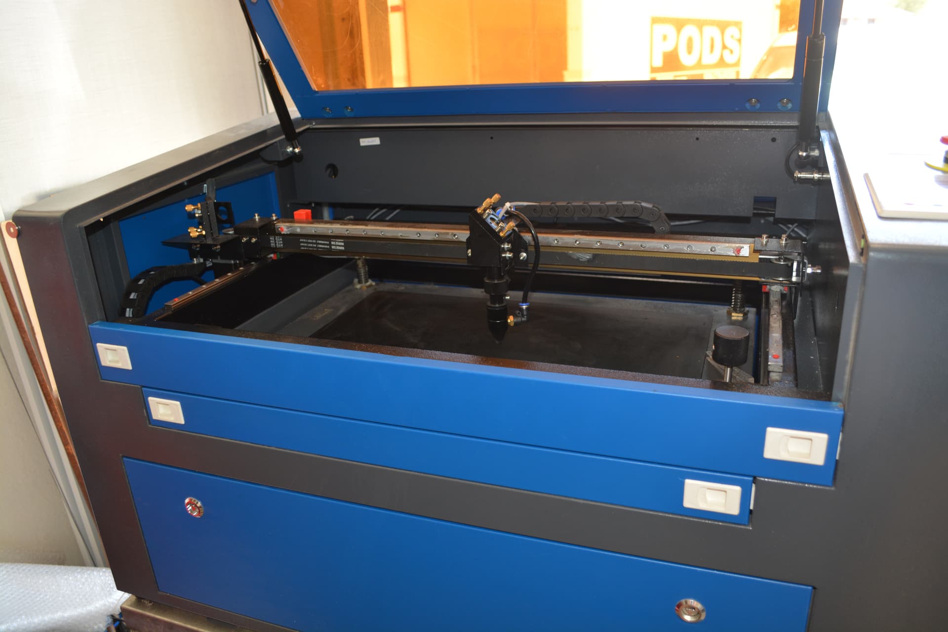
Finally got it pretty close to centred and fired up the machine for a test run with the new tube. It is still producing the dots instead of a constant line and the newly installed MA meter isn’t showing any movement while cutting. I hooked up a double A battery to it as a test and the meter moves though not while the machine is running… I’m out of ideas so anything you can recommend will be great. Thanks
The meter is not wired up correctly… I has to draw current when it lases, even a very minor amount will move the meter to some extent.
The meter should be ‘in line’ with the cathode (negative) end of the hv return line
Can you fire it at 50% power from the console and see what kind of mA you draw?
I find it hard to believe nothing has changed with a new tube, since the original was obviously toast.
Where is your beam hitting the mirrors, especially m1.?
![]()
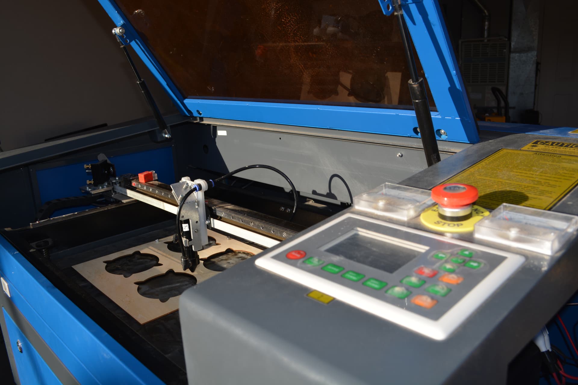
Beam is hitting centre on m1 and im sure the wiring is correct for the MA meter as the tube is firing…i will recheck the wiring to ensure it has correct contact once the machine has been unplugged for a couple hours and will upload a photo of the wiring when i get a chance…
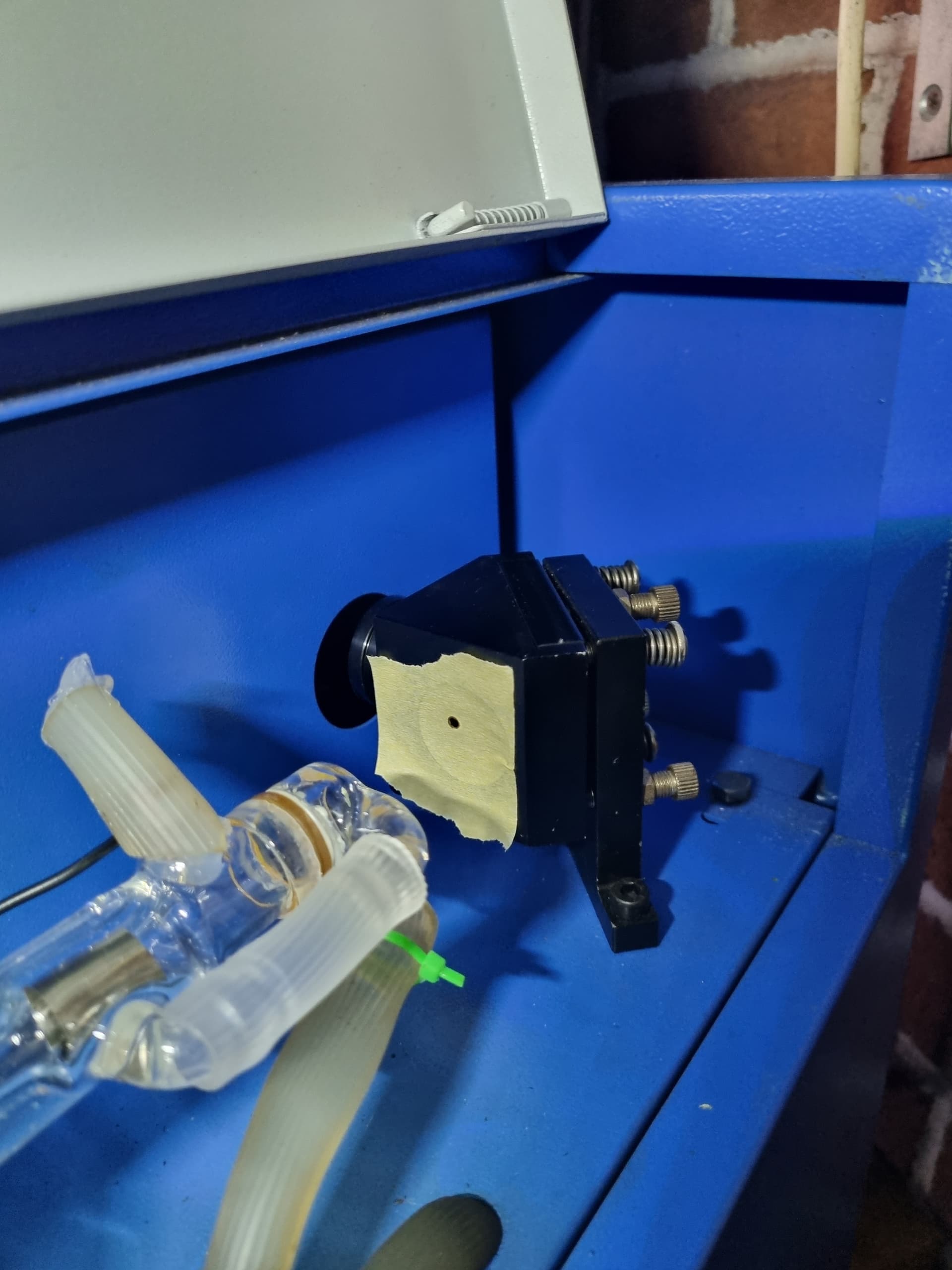
I am still perplexed to why it isn’t cutting correctly… attached is a close up image of 60 speed, 55% power and 6 passes of 3mm mdf… and still couldn’t cut through…
The tube must draw current for it to operate.
Two things I don’t think I mentioned was that your tubes coolant exit hose should be vertical to encourage an air in the system to evacuate.
Your ‘dot’ on the target should be much lighter, so you can actually see how the beam is performing. A light brown is all you needs. When it’s too hot you ‘miss’ things…
Simply, If the tube is working properly, and there is proper optical alignment, they work.
You are missing one of these items. Generally it’s alignment/dirty optics that causes these failures.
I can only suggest the alignment is off somewhere. As a new user, this is where most people have their issues. Until you get the ‘hang’ of it, it can be frustrating. I fought with this also, as had anyone with one of these machines.
Maybe it would help to step through the alignment with you.
Post your targets on each mirror and head/table so we can see where they strike. Back off the power, you might have to pulse multiple times to get a ‘dot’ but keep it light brown. A dark spot can obscure issues.
I think, at this point, it’s an alignment issue… Don’t really know what else can cause this.
Good luck
![]()
Thanks Jack for your time in assisting to help - as you have more patience than me at this stage ![]()
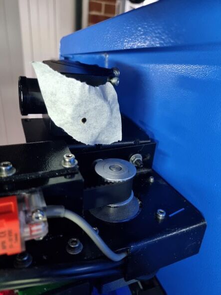
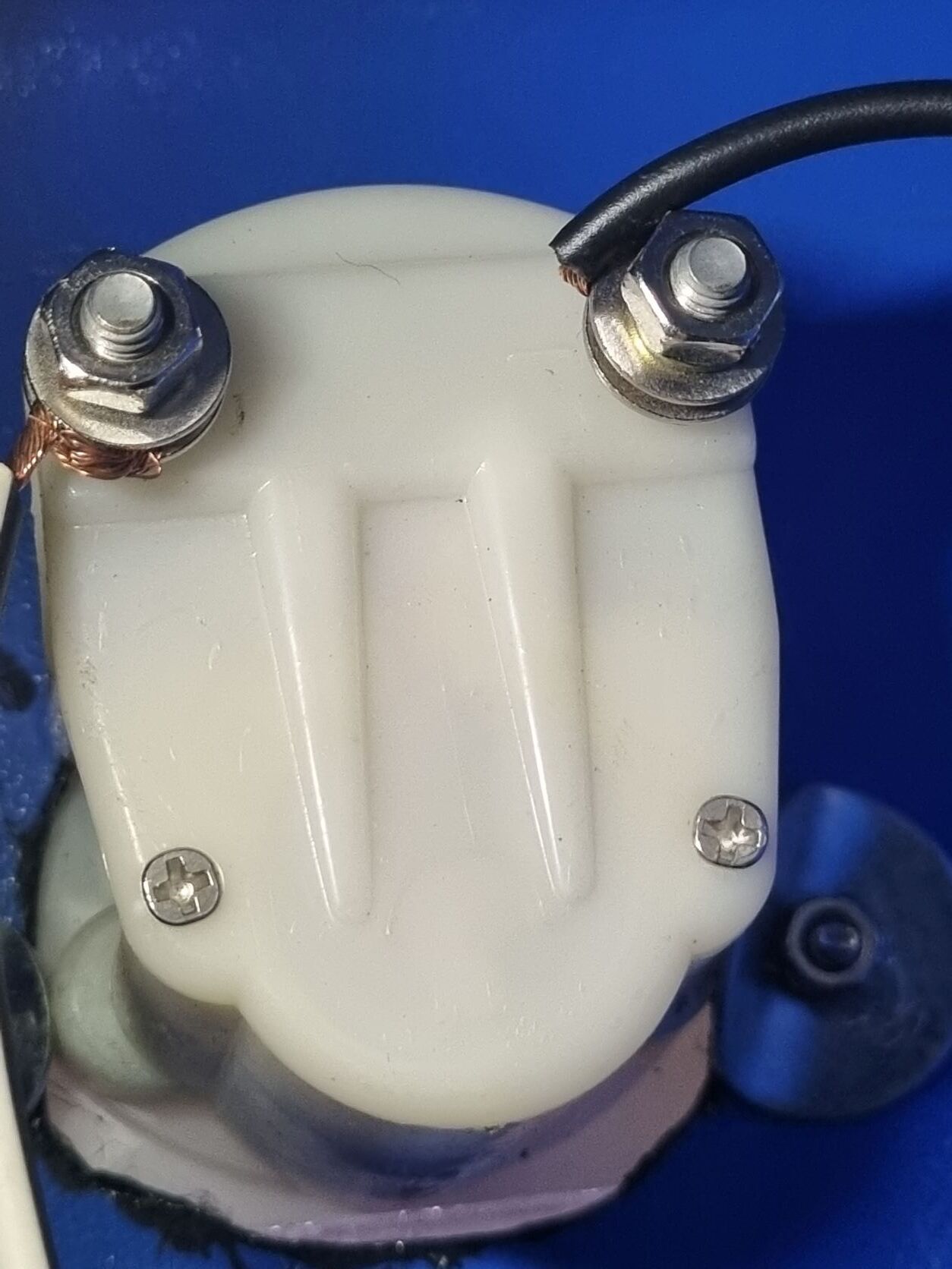
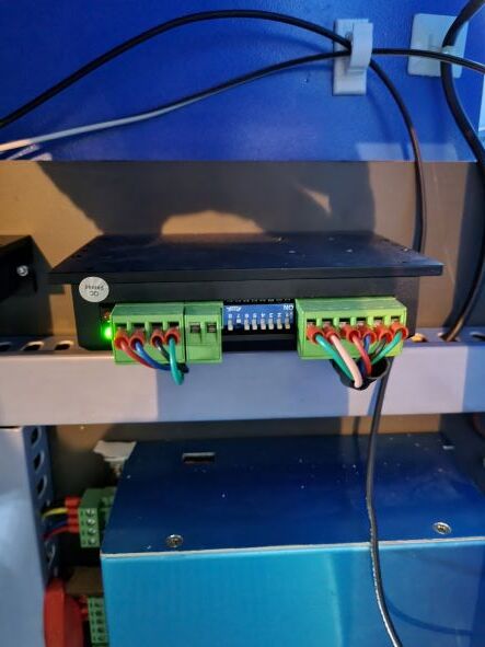
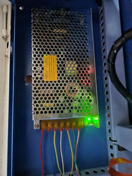
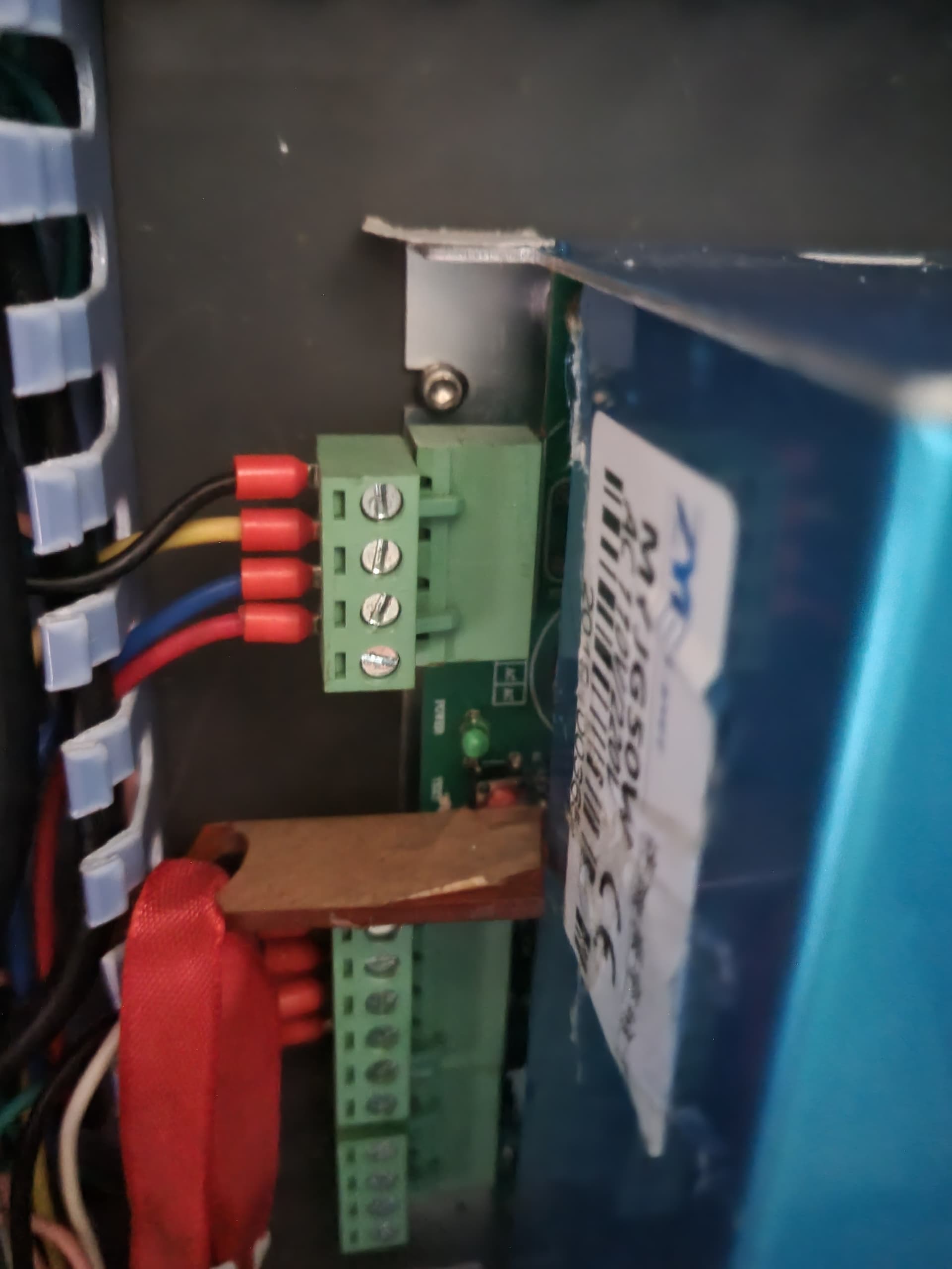
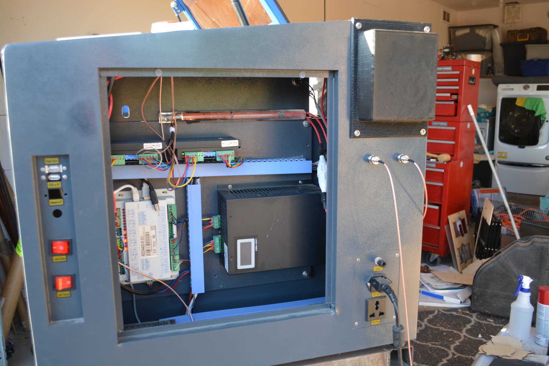
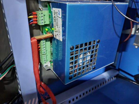
attaches are the images of each mirror, computers, power supply and wiring for the MA meter… I noticed that the mirror alignments are not centre on mirror 1 and 2 though it is as close to centre as possible on mirror 3. It is coming out centre from the nozzle though i forgot to take a photo.
The MA meter is wired accordingly…
White/Black cable coming from Negative anode of tube and going to positive point on MA meter, Black cable going from PSU (L) and going to negative point on MA meter.
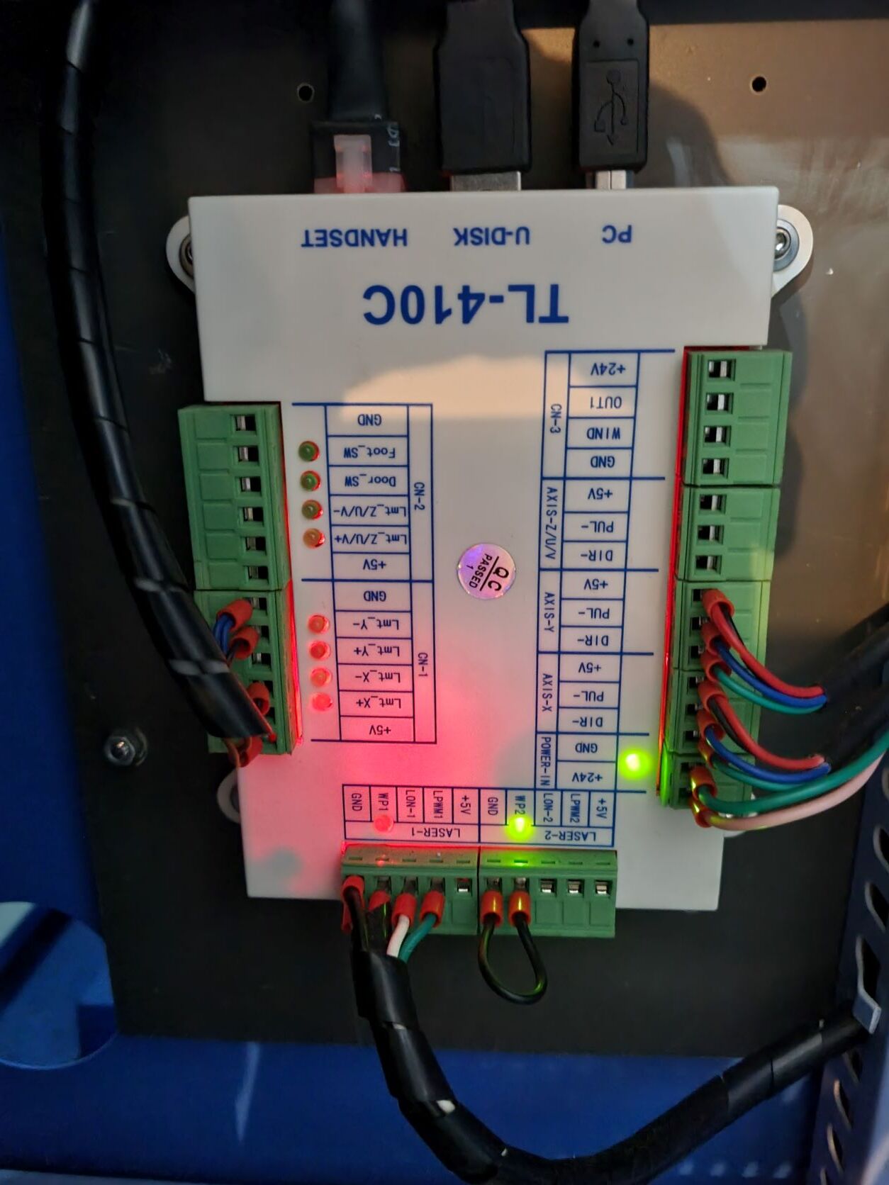
The photos of the modules are while the machine is on, there seems to be red background light? on some of the sections - not sure if this is normal - Any help would be greatly appreciated as I really enjoyed it while it worked and with no local support it is difficult. Thank you again and i hope the images will assist.
The cathode is the negative side of something… It is the ground return line for the lps/tube. The anode is where the high voltage positive side is feed. The meter should be inline between the cathode and ground. The negative side of the meter needs to go to ground. If L on the lps is wired to ground, that should be ok, but it isn’t a good way to phrase it… since the lps is not really involved.
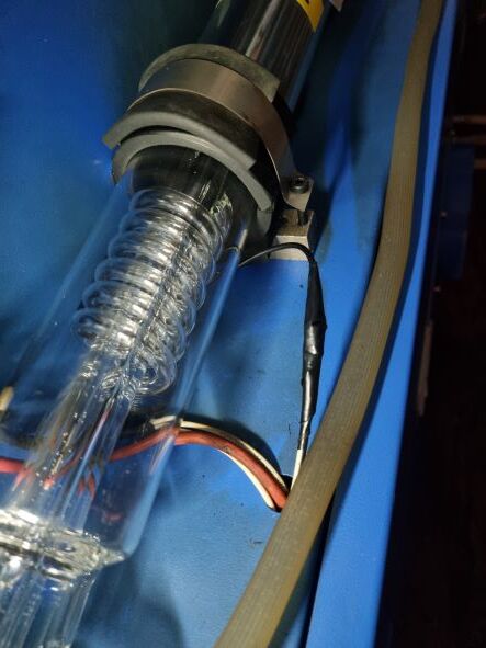
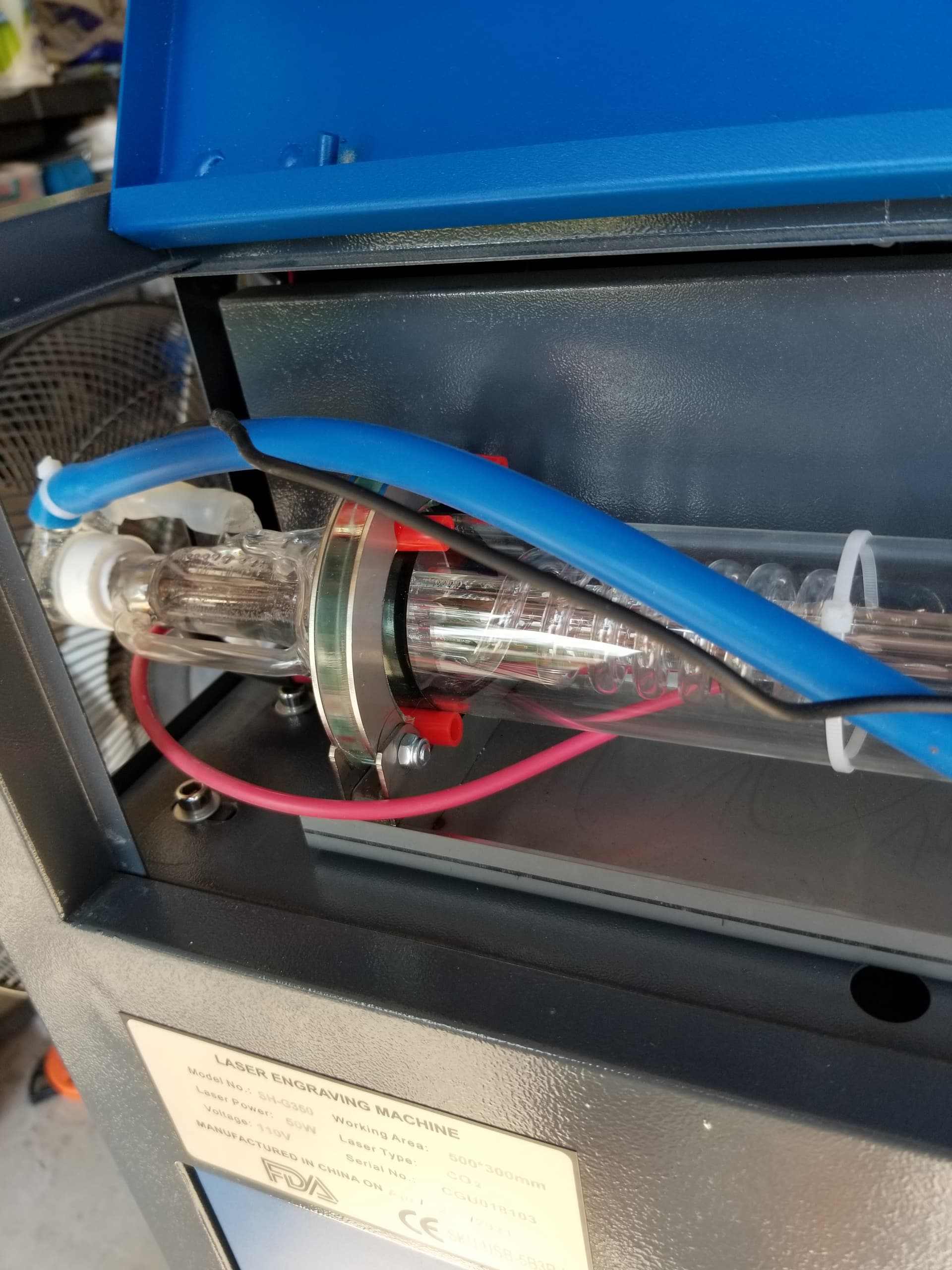
I keep meaning to advise you to rotate the tube so the output is up. This allows any bubbles to exit the tube. Yours appears to be pointed down (post 22), you can see mine on post 11 is pointed up.
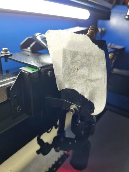
Can you center m1 any closer?
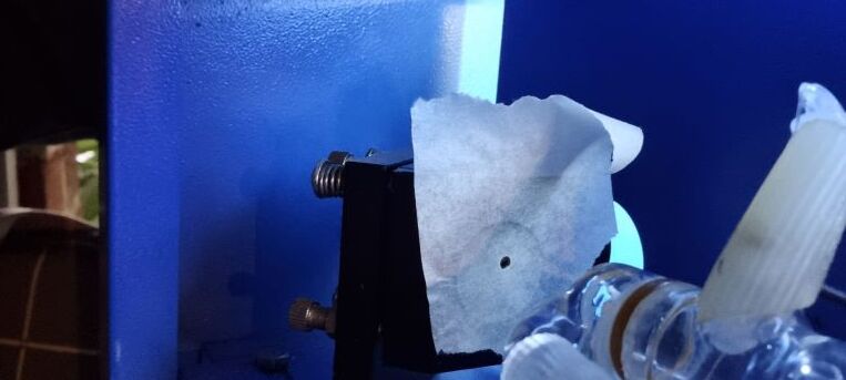
Your marks need to be much lighter, check out the target from m2 I posted back in 16. It is two burns, one as close as possible to m1 and the other at maximum distance. Yours are so dark I really can’t tell much from them. Are they two burns?
WIth your type of head the center of the hole isn’t nessarily the center of the mirror.
What’s most important with m3 is that the reflection goes straight down to the table in the center of the lens tube. Not if it’s in the center of the mirror… You have to ‘catch’ the beam with the head at the point where the long/short distance converge from m2.
Hang in there… ![]()
![]()
Thanks Jack, im still hanging in there …hahaha
i cant turn the tube any further as the anode and negative cable will then be too close to to touching the body of the machine. i had aligned the mirrors as good as i can and got it pretty damn close at 80% of the bed which i am satisfied for now.
Well, i decided to attempt to cut Perspex and it worked fine. 3mm perspex cut using 1 pass at 65% power 10mm/s speed - so not sure why it isnt cutting through birch/pine.
The MA meter still isn’t operating, i simply cut into the black wire coming out of the laser and ran one end to the positive terminal of the MA and ran a new wire from the negative terminal of the MA to the other end of the black wire which runs to the “i guess ground power supply”… any feedback on this would be great as i would like to have the MA meter working to ensure i don’t over run the tube.
Anode is the positive and the cathode is the negative side. The cathode is virtually at ground potential.
My hv feed lay right against the machine case… The tube position is important… all the hv should be well insulated as I’m sure it passes through the machine.
Not good planning. You need to know if it’s the proper return line.
If the tube is lasing, it’s drawing current and you should read it.
It’s in the wrong return wire or it’s somehow shorted.
If you have an ohm meter, measure the resistance. Doubt it will draw 30mA, but it will tell you if the meter is working.
![]()
I will adjust the tube as per your photo this week, thanks for the image and reassurance it won’t be an issue… I have just rechecked all the wiring and it is going to the correct return wire and the machine is firing correctly…
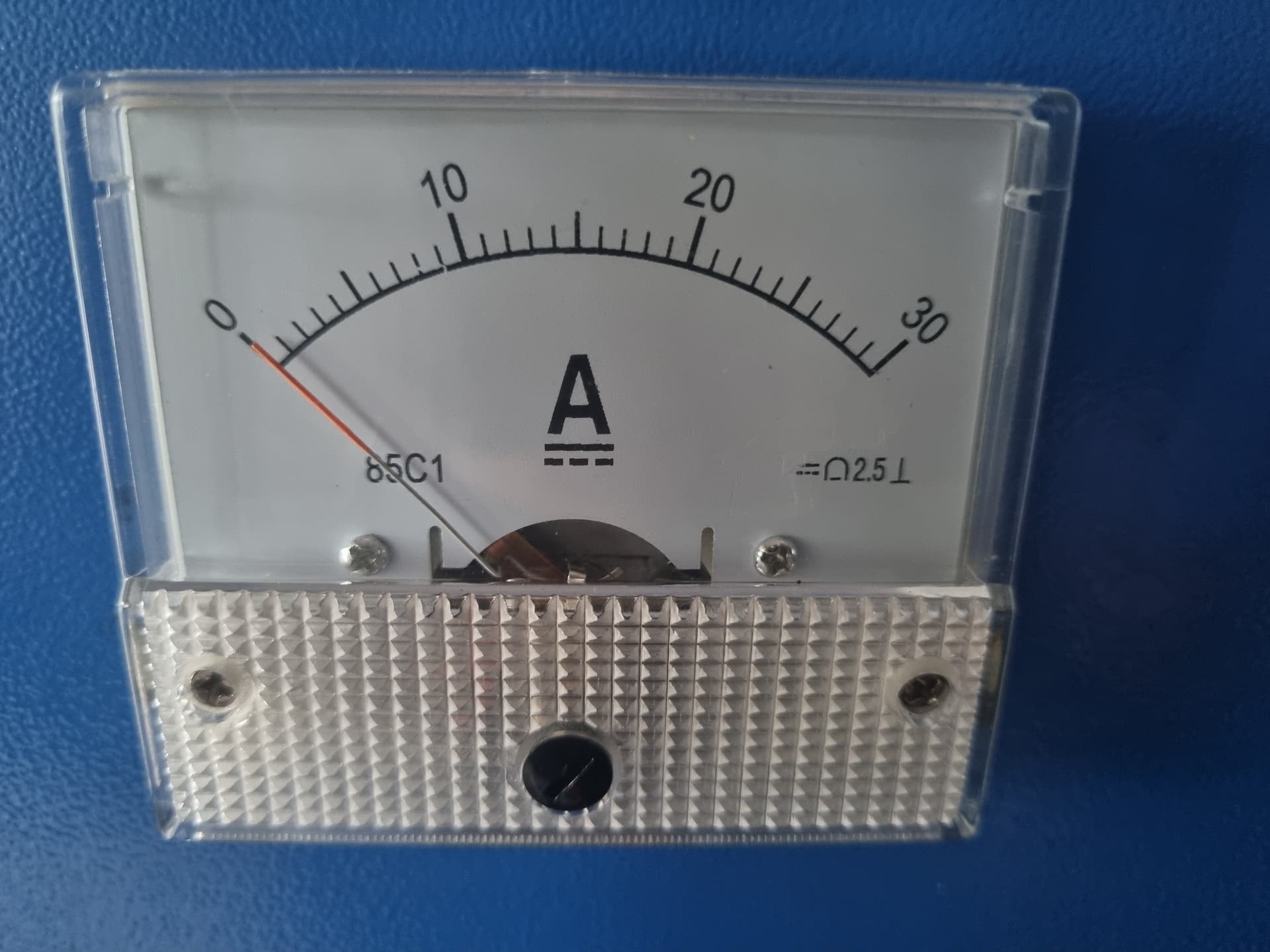
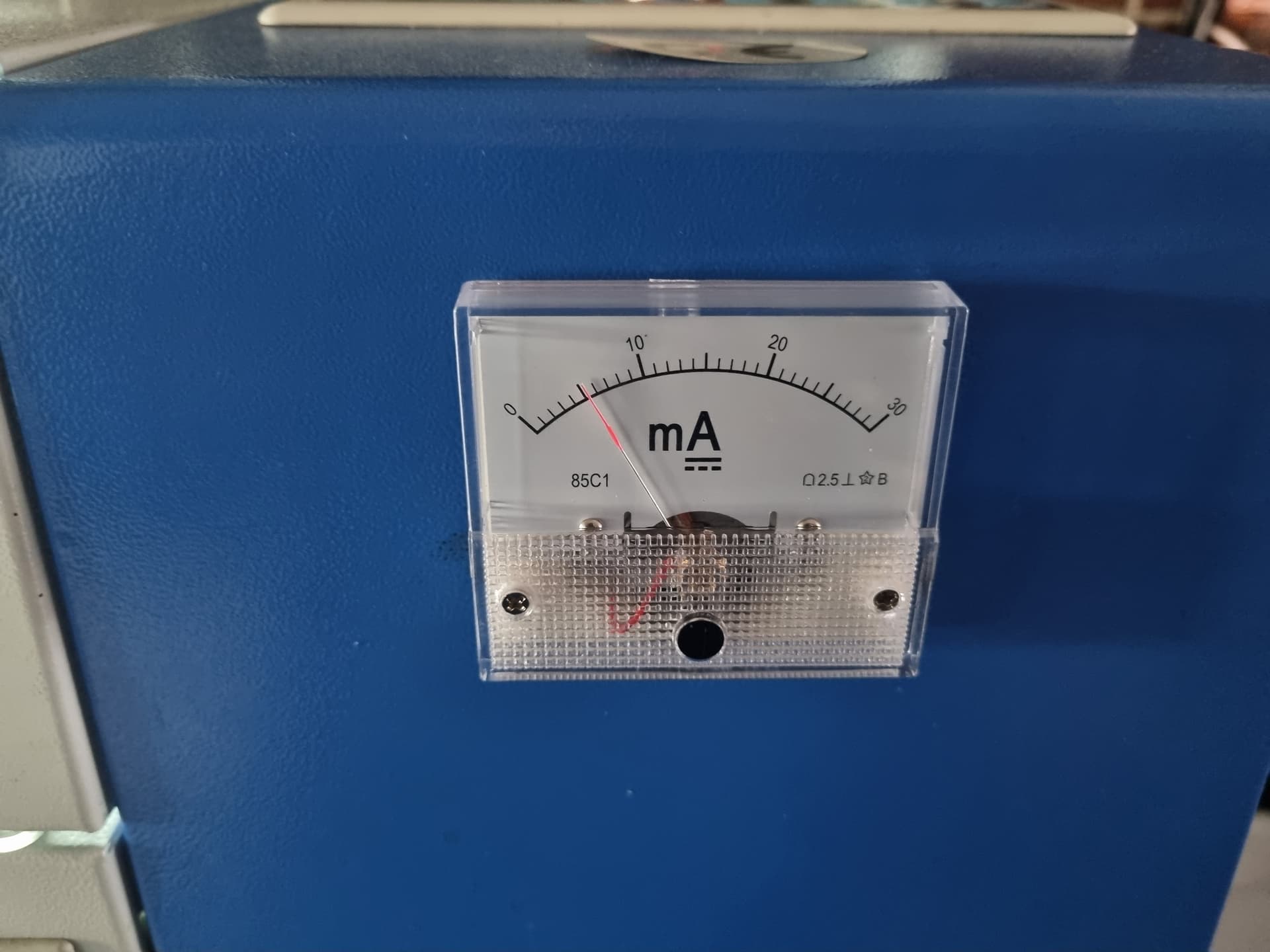
The ma meter i purchased is the following and i tested it by connecting a Aa battery to it and it moved in the right direction, could they have sent out an ac instead of a dc by mistake?
It is connected to the black wire which is at the top of the image, i followed the following instructions and have tried switching the connections around from positive to negative etc with no reading… unfortunately i don’t have a multimeter to test anything with as i don’t think my skill level is there being a lady ![]()
Yours is a 30 amp. What you need is a 30mA. It is 1000 times more sensitive.
If you noticed the link shows
Like this from Amazon.
https://www.amazon.com/uxcell-Current-Ammeter-Circuit-Testing/dp/B07DH77XBS/
Probably connected correctly… get the correct meter…
Don’t stick a battery across a mA meter. Amp meters, not matter full amps or milliamp, measure current flow through them, unlike a voltmeter that shows potential. With a battery it would be like a short and full battery current will flow through it. It can damage sensitive meters like these mA meters.
I wouldn’t think a normal household battery would move it.
Nice job on it’s install, looks clean and professional.
![]()
oh my gosh!!! how embarrassing
i will order a milliamp meter this time… thanks for the comments on the install… it is the one thing I was confident on completing since this tube issue saga has started - I really appreciate your support, time and guidance
No perspiration
Good luck
![]()
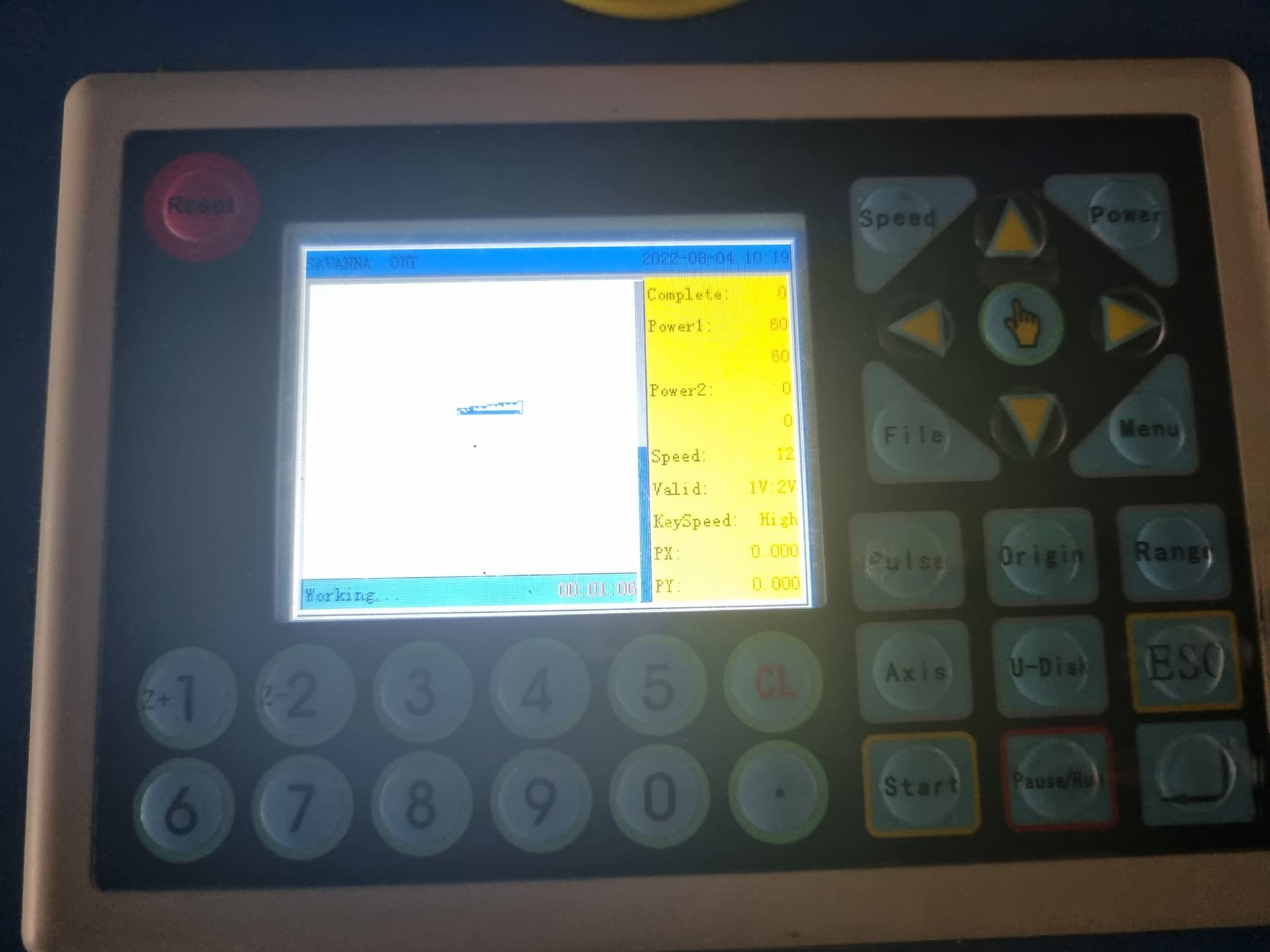
Got the milliamp meter working and slowed down the speed to 8 to 12 and it seems to be working OK now… at 60% power the miliamp is reading 6… does this seem low for 60% power in your opinion.
Keep in mind that a laser only lases at 100% power… there is no ‘real’ power control. At 50% power it will ‘lase’ at 100% power for 50% of the time, that is your power control.
Let me give you an example of an analog meter…
Analog meters read a voltage/current, it’s the ‘root mean square’ or ‘rms’ voltage. For practical purposes it’s pretty much the average voltage/current.
For example, if there is a 5v signal and it’s 5volts 1/2 the time and zero the other, it will read an rms 2.5volts. This is how your pwm works. If set to 50% power, which is a 50% pwm signal the current will read 50% of what the ‘on’ current is because it’s only there half the time.
We can compute the actual ‘peak’ current by using 6/60 = x/100 or 60x = 600. That makes the peak or actually ‘lase’ current at 10mA, which is too low for a 50 watt tube. Mine is set for the manufactures ‘test’ maximum current specified for the tube. It’s 21mA about twice of what you are getting.
Can you look at the lps and see if it has an adjustment?
Seems like you are getting about 1/2 the current. you should.
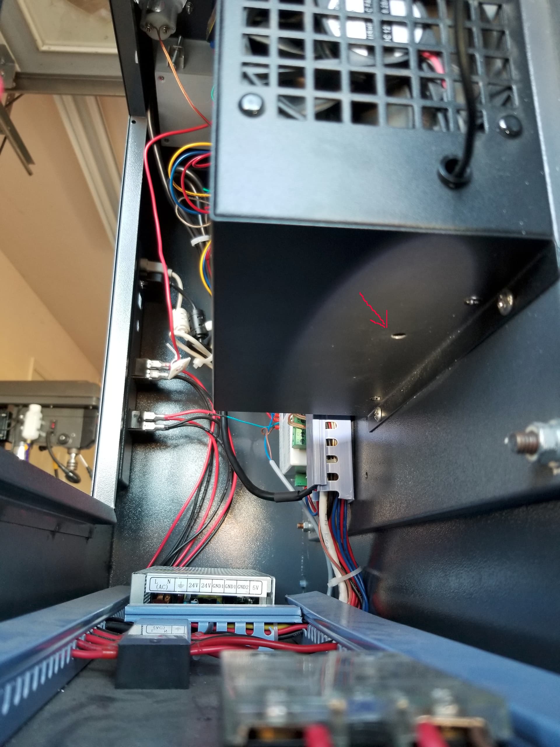
On mine, you have to be a contortionist to just get to the ‘hole’ and impossible to read the mA meter when you can physically get to the adjustment. The red arrow is pointing to the lps current adjust ‘hole’ This photo is from the back access panel with the camera inside the bottom of the electronics cabinet looking towards the front of the machine.
A good procedure is to draw a line long enough for a stable meter reading. You can remove the lens if you wish, less worry about the ‘beam’ damage if you wish.
Run the line at 50% power and adjust for 1/2 maximum tube current.
Make sense?
It’s nice to have some idea about how much power you actually have. Mine is a ‘China Blue’ 50 watt. It measures 44 watts.
I have a Mahoney wattmeter that I use monthly to look for anomalies in the beam power.
Russ Sadler has a lower cost unit…
Here’s a couple of links to videos by Russ Sadler and show his ‘dohickey’ for power measurement. The first is the nitty gritty of it, the second is how an earlier version that details it’s operation and power meters in general … The second is a more technical description…


Good luck
![]()
you are very knowledgeable thank you
i have the same laser machine and ebay tube as this video, it seems he is getting approx 8ma on 60% power… i will try your recommendation at 50% and 80% and advise the reading. i will also look for the LPS adjustment hole. Thanks again

Seems strange that at 98% power he’s only getting 36 watts?
Technically you have to plot it to see what it’s doing. I did that, but think it was pretty much a waste of time for me as I ‘fool’ around with it and the settings quite a bit.
There are some devices, such a tunnel diodes and some lasers that are ‘negative’ resistance devices. Meaning an increase in voltage doesn’t necessarily result in a higher current draw.
Mine evolved
to this, so far…
They seem to ‘evolve’… ![]()
![]()
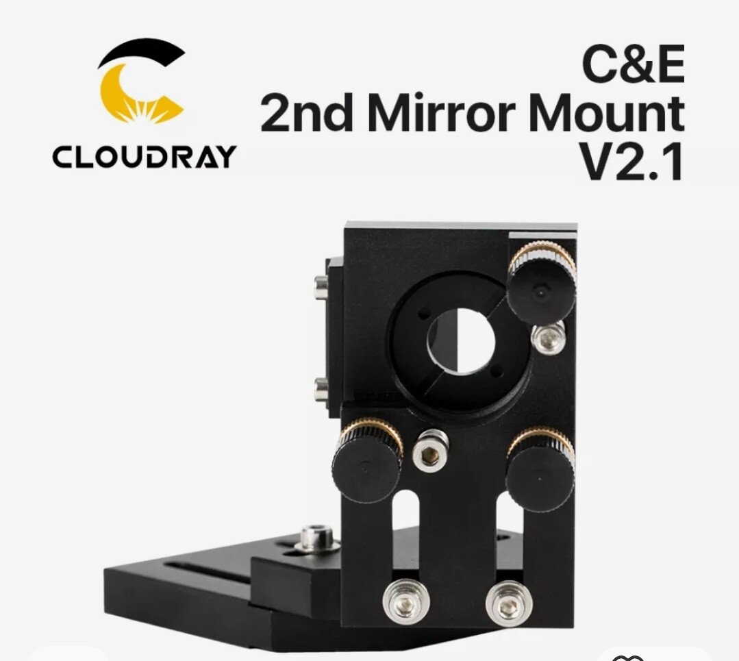
Wow, that looks neat… can you advise where you purchased mirror 2 mount from or the model version as i purchase a cloudray model as per image and it didn’t fit… the original one is extremely difficult to align as the screws etc are very stubborn… i like that you extended the rear to accommodate a larger 60w? Tube…
My perspex lid is also clear, is there a recommended tint i should apply to it or is the standard clear perspex sufficient? I noticed your one was orange and i always wondered if that was needed or due to the wave length the standard perspex was enough…or even automotive film?