If the lens is wobbling around while traveling parallel to the X axis, any motion in the X direction will be pretty much invisible: if the beam goes backwards or forwards, the trace will be marginally lighter or darker.
But if it wobbles in the Y direction, then the beam will burn to one side or the other of the center line where it should be, which could produce those worms.
Come to think of it, in Dot Mode a wobble in the X direction could produce irregular dot spacing, which is kinda-sorta what appears in the bottom track.
I’m not convinced, but it’s certainly worth checking all the doohickies on the laser head for a snug fit.
I’m so glad you guys have raised the worm issue. I have no experience with lasers at all and don’t know what I should be expecting in terms of results. To give perspective the laser was £6k Sterling and it was new March 2022. However, I have not started using until about 4 weeks ago and was immediately struck by lack of quality on attempting to picture engraving.
I will investigate the mechanical setup further. There’s no way I would have know that the wobble you refer to should not be an expected result. I would have put it down to units limitations. Really appreciate your input. Thanks.
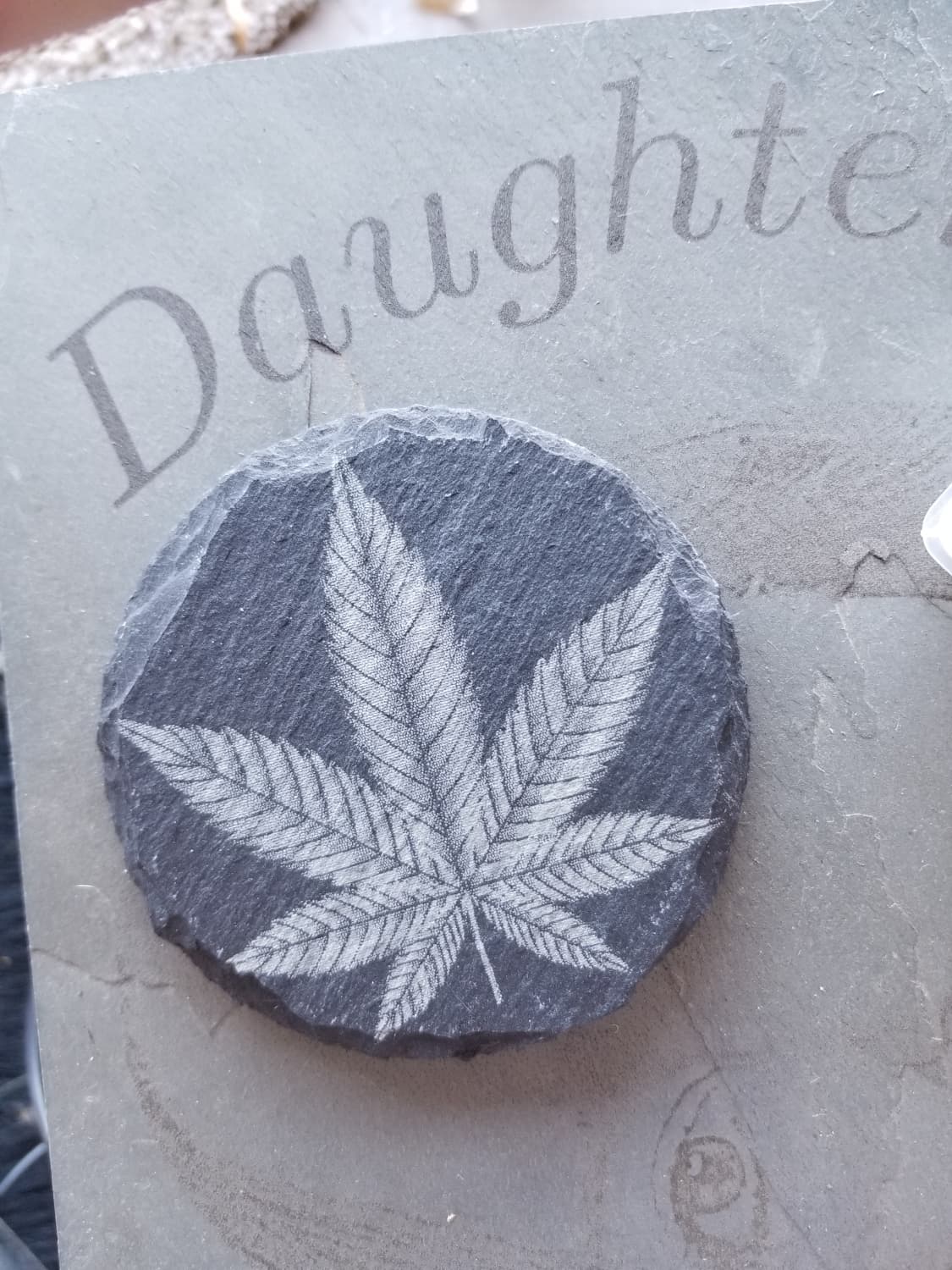
This one was done on the fiber… this has a smaller dot, but the material, is generally the what sets the dpi limit … in the end it will be laser dot size and material that will decide the best dpi.
Given a loose tube rattling around in the back, it should be awful.
With that snugged down, the results look pretty good and we’re quibbling about details.
The scan interval depends on the width of the surface damage in the target: 0.15 mm is an itsy too wide for the grayscale material, but might work fine in a different material.
At some point you should explore Dot Width Correction for images; I don’t have a lot of experience, but it’s apparently the ticket for crisping up the contrast:
This laser everything video talks to the Lightburn developer of dot width adjust at about 20:18 into the video… good explanation… also a very good video on how to set up the proper dpi for a any given material/laser.