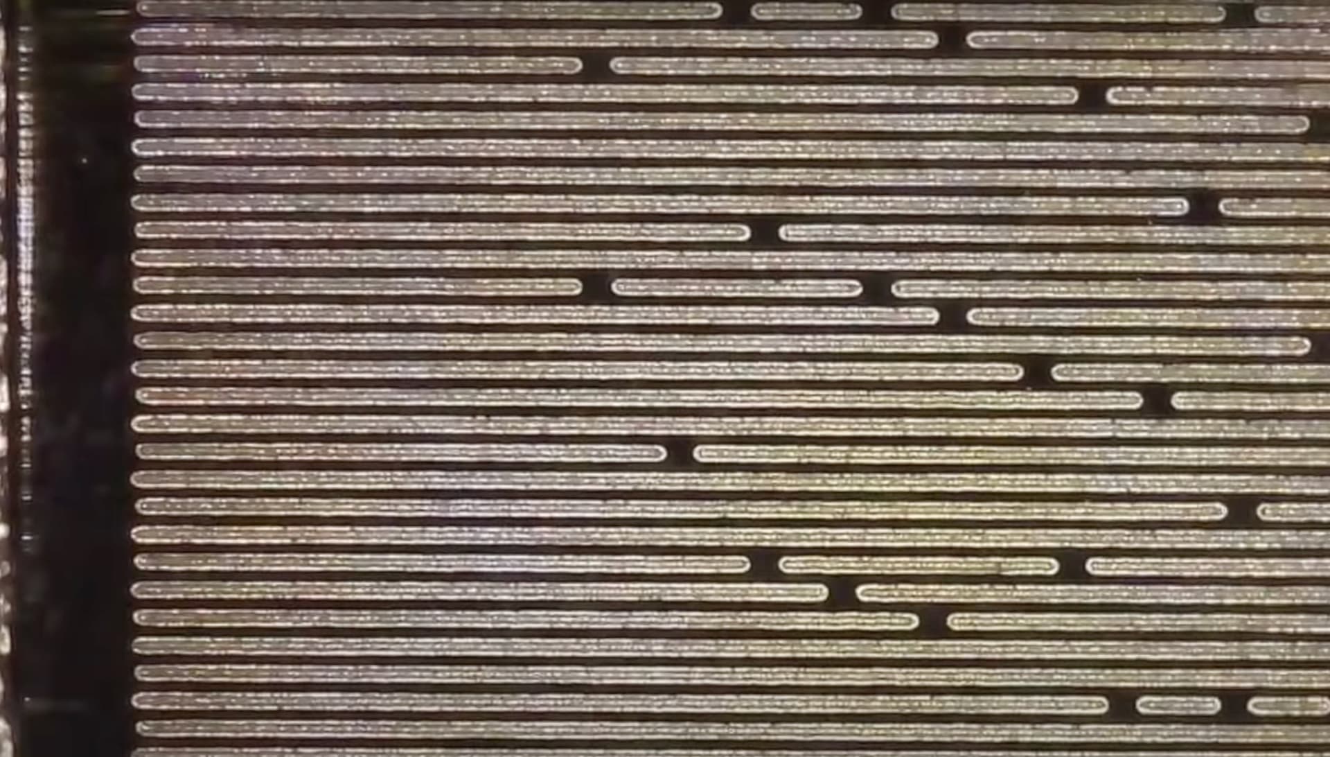
Hi great post. I have an 80w CO2 laser. Been following your recommendations. When I look at engraved lines in the grayscale test using a microscope they are extremely poor quality compared to your examples. Would this be a laser timing issue or just a limitation of the device do you think?

Start with focus… You should be able to make single straight lines.
It looks like focus, so I’d start there. A complete alignment check is usually a good idea… just need to check to ensure it’s not off.
Also check for any lose mechanical parts. The line, isn’t straight, and it doesn’t look focused. You may have multiple issues.
Probably a good idea to move this to it’s own thread… Your laser is nothing like the AtomStack, so people that might see it if it was under Ruida controllers.
Maybe @BillieRuben can move it for you… You can reference this thread if you wish.
Good luck
![]()
Hi Jack, thanks for this. I have just found this forum so great to get such a quick response. I have done a full alignment check and all the mirrors are aligned. Also double checked the the focal length with a ramp test and all checks out. The images are at 1000x magnification. I was hoping someone could confirm whether a CO2 laser should get the same kind of lines as a diode laser. These are the shots from a diode. When you say move to a new thread, how do you do that?

If the question is for a CO2 laser then it should not be under AtomStack A5 Pro+ label…
I think you can just ‘edit’ the original post and change where it goes… If you have issues moving it, then one of the Lightburn people can probably do it.
I though you had fixed the issue looking at the photos, but realized it was the led.
Your focus should be about that of the led laser. Most co2 can focus to at least 0.1mm which is good for 254dpi… with the right lens even smaller.
Can you post the photo of the ramp test?
![]()
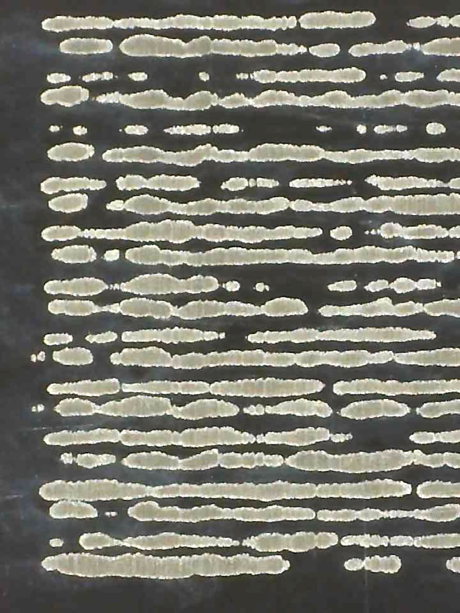
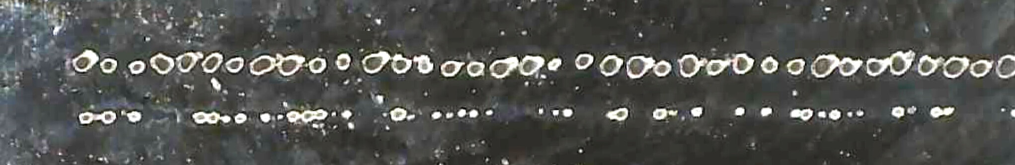
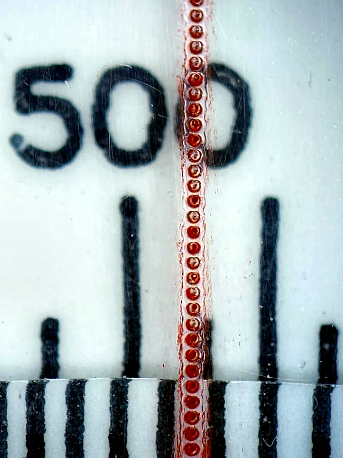
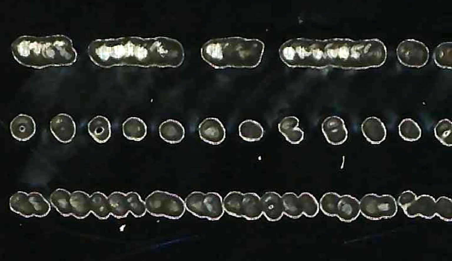
Hi Jack, thanks again for getting back. I have attached the last ramp test. The laser has a 1inch lens (22.5mm). I have also attached a dot test for want of a better description. The top row of dots are 0.1mm diameter and spaced with 0.1mm interval. The bottom row are 0.05mm diameter, spacing at 0.05mm. Both were cut at same power. It does seem to indicate the laser is not firing with consistent energy as some of the 0.05mm diameter dots have not burnt at all and there are clearly different diameters in the 0.1mm dots. Have a great weekend.
Maybe @JohnJohn can split this thread… I don’t think, as users, we can do anything about it.
Nobody with a machine similar to yours is going to read this or at least there will be less, everybody will think it’s for an AtomStack…
You have never mentioned what speed you are running.
Most of these machines have an lps (Laser Power Supply) that creates a high voltage to cause your tube to lase. This is for a DC excited tube. It has to go from a low voltage to up around 30kV to cause your tube to lase.
This response time of the lps will determine how fast your laser can fire…
All of these I’ve seen for these machines, if stated, is 90% of the placard voltage <= 1mS. If it’s 1mS then the best you can expect is to be able to toggle the tubes output is, in 1S, 1S/1000 (= 1mS) or 1000 times a second for 1000dpi.
You can see that speed and response times are important… I don’t know of any dc excited, co2 that can respond any faster, they might exist somewhere…
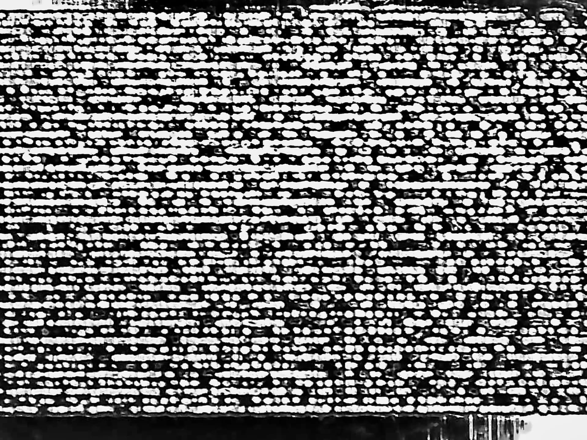
Agreed, if you look closely at your ramp test, I think you’ll see it’s acting like it’s pulsing instead of a continuous wave (cw) output. If you can interpret the dot pattern, I blew it up…
I think your ramp test indicates you have a problem from the lens back towards the tube.
I have a compound lens, that’s not as short as yours and it’s a much more fine line. Yours seems like there is an issue with the beam, alignment or it’s cleanliness.
I’d start at the beginning and when I get to the problem I’d stop and fix it. ![]()
- How long have you had this?
- full alignment, including the beam pattern before m1 (mirror 1) TEM mode. The beam must be in TEM0 resonance for it to operate properly.
Do you know how to align it or confirm it’s alignment?
Lets hope this gets moved, so you get feedback from others…
Good luck
![]()
I have moved this thread into the Ruida controlled CO2 laser engraver channel.
That’s why we do it. Thanks for the heads-up.
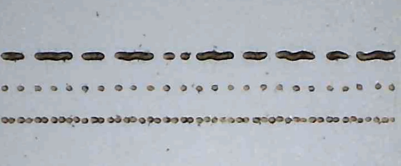
Although this isn’t quite comparable, here’s a row of much nicer dots from a 60 W (claimed) laser:
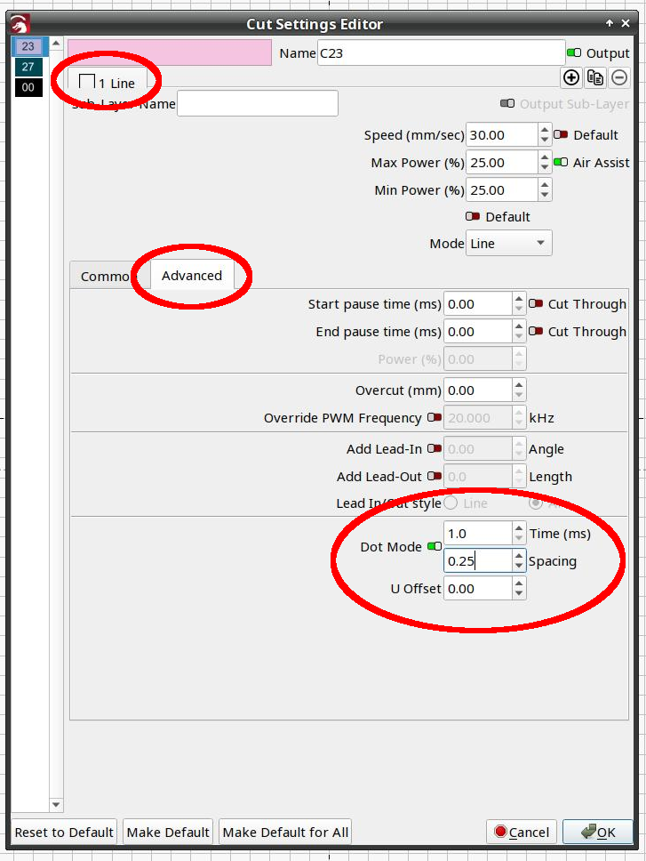
Those were done in Dot Mode:
Dot Mode layer parameters:
- 2 ms pulses
- 0.25 mm spacing
- 20% power
- set speed 100 mm/s, actual around 5 mm/s
I don’t know if yours were done with Dot Mode, but, if not, it’d certainly be worth trying to see if it looks better. Then we can compare results and maybe reach some conclusions.
Some background and other power variations on my blog:
Hi Ed, thanks for the image. Those marks a far more consistent than mine. I’m just checking into all the information that Jack provided regarding the limitations that the laser firing speed imposes.
Thanks Jack. The thread has been moved. I understand your thinking on the laser firing speed. Just taken the machine to bits so I can see all the various components and get some specs. It is an Oculus 6040 (600mm x 400mm bed) from OPUS CNC based up in Durham, England. It’s a bench top, but you need one heck of bench, it weighs more than 300kg. Thanks for pointing me to what will clearly limit potential resolution. The speed for the dot test was 100mm per second. Do you think the 0.05mm diameter dots indicate that the 6040 can resolve a 0.05mm dot and retain a 0.05mm gap, but obviously not consistently? In the manual it recommends a line interval setting of 0.035 for raster engraving images on acrylic. Thanks again.
You can’t really tell what kind of a dot you can make if the machine isn’t operating correctly. Yours is clearly got an issue with it’s optics/source…
The ramp test isn’t bad, but the output of these dots look unfocused.
Don’t know where you got your source… or how it’s configured… but here is a dot test from Russ Sadler and how to interpret it… It’s under the heading Interpreting The Dot Size Test results
When you load this, use the zoom to frame selection ![]() to see it…
to see it… ![]()
Are you running in pass through mode on the layer?
![]()
It turns out the power supply puts a rather low limit on the overall response time, on the order of 250 Hz for PWM input. That’s not the PWM carrier frequency, which is typically 20 kHz for Ruida controllers, but the rate at which the laser power can change.
The overall risetime is around 1.5 ms, so the dots can’t be much less than 4 ms “wide” to have reasonably steep sides and a flattish top. That means a 0.05 mm dot requires a scanning speed around:
12.5 mm/s = 0.05 mm / 4 ms
Which is sufficiently lethargic to incinerate anything you’re likely to be engraving and so slow you’re likely to not believe it.
I didn’t believe it, either, so here are the measurements & pix:
The linkies there take you to the background on the test setup & suchlike; it took me a while to work around to those conclusions.
So a CO₂ laser can produce high resolution images and run at high speeds, just not both at the same time.
Hi Jack and Ed and thanks for your help.
I have run Gareth’s dot test. Seems like this device is producing a dot size of 0.2mm.
OPUS are also running test on another 6040, same material same test files. Should hear from them a bit later.
I’m using Lightburn Ed, does this have ‘dot mode’? I can’t seem to find that. It does provide ‘Threshold’ which is either on or off for black or white.
I’ve checked the laser power supply, Model: HY-T80 so Response Speed is ≤1ms to 90% of set power. Should be able to run at 200mm/s by Gareth’s info, maybe up to 400mm/s.
The Ruida Controller is model RDC6442G-B.
Going see what some slate engravings look like at 127dpi.
Thanks again for your input.
Got you, thanks for that. Another thing learnt:-)
Are you running the test with pass through enabled on the layer?
![]()
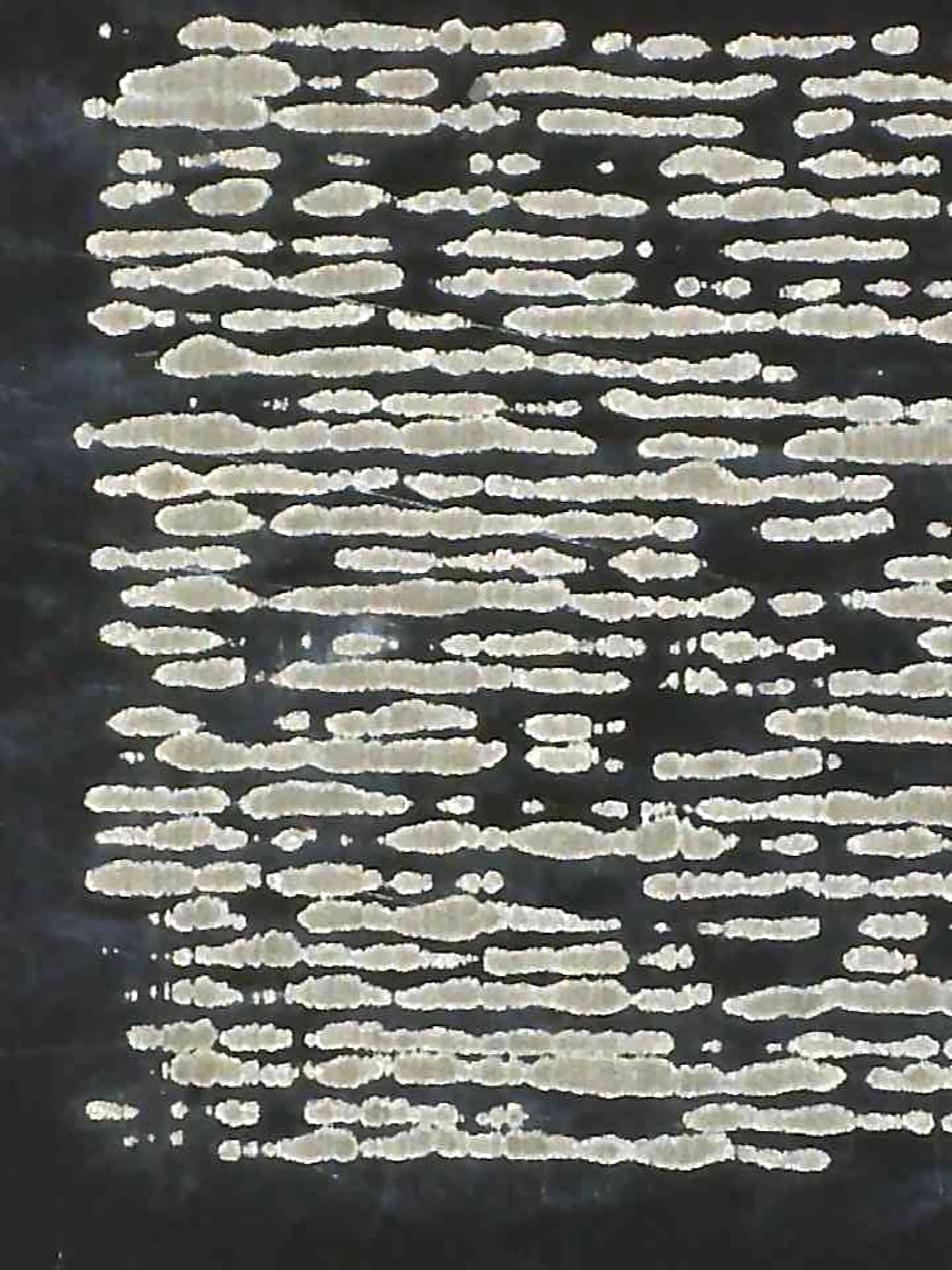
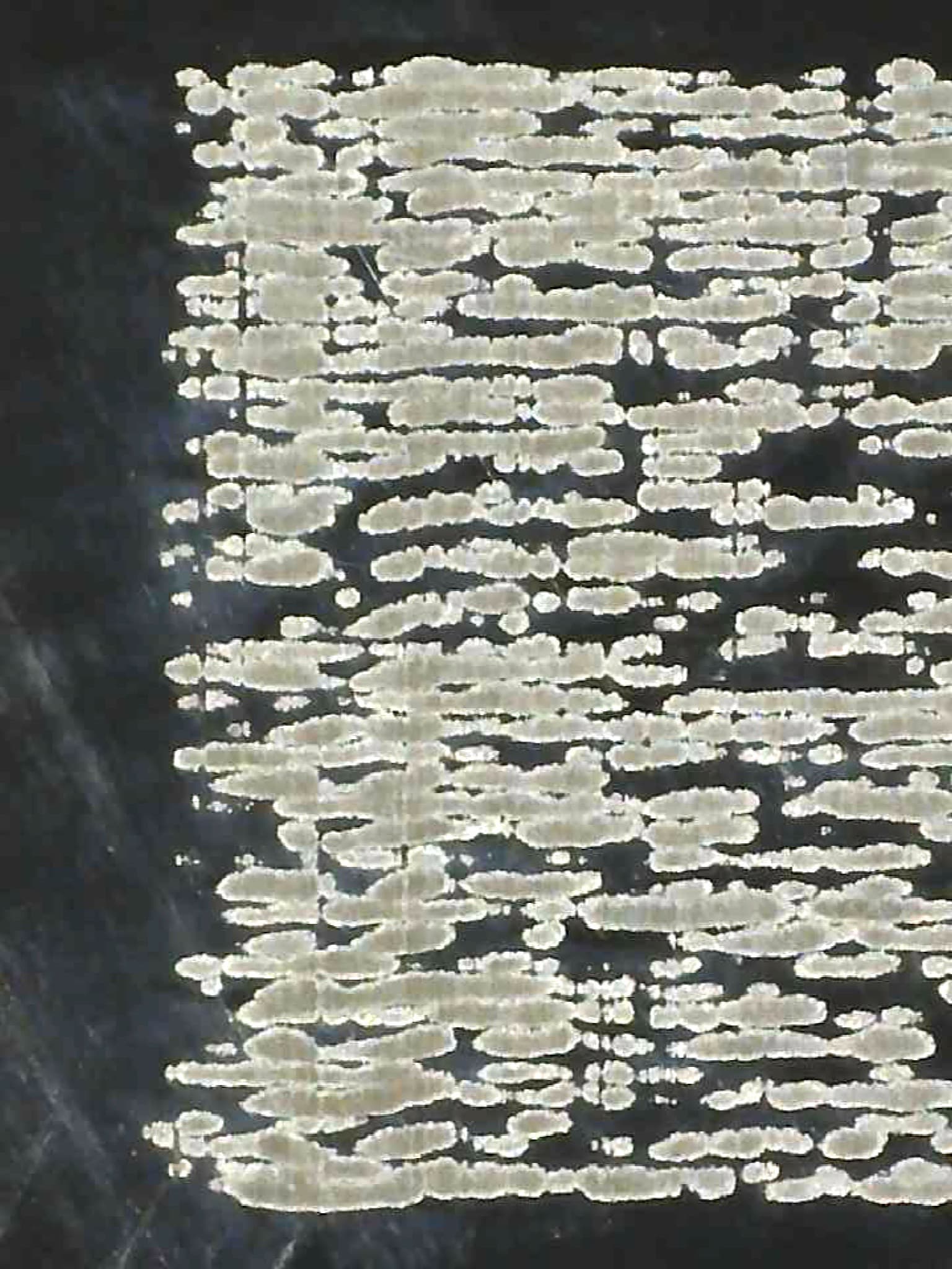
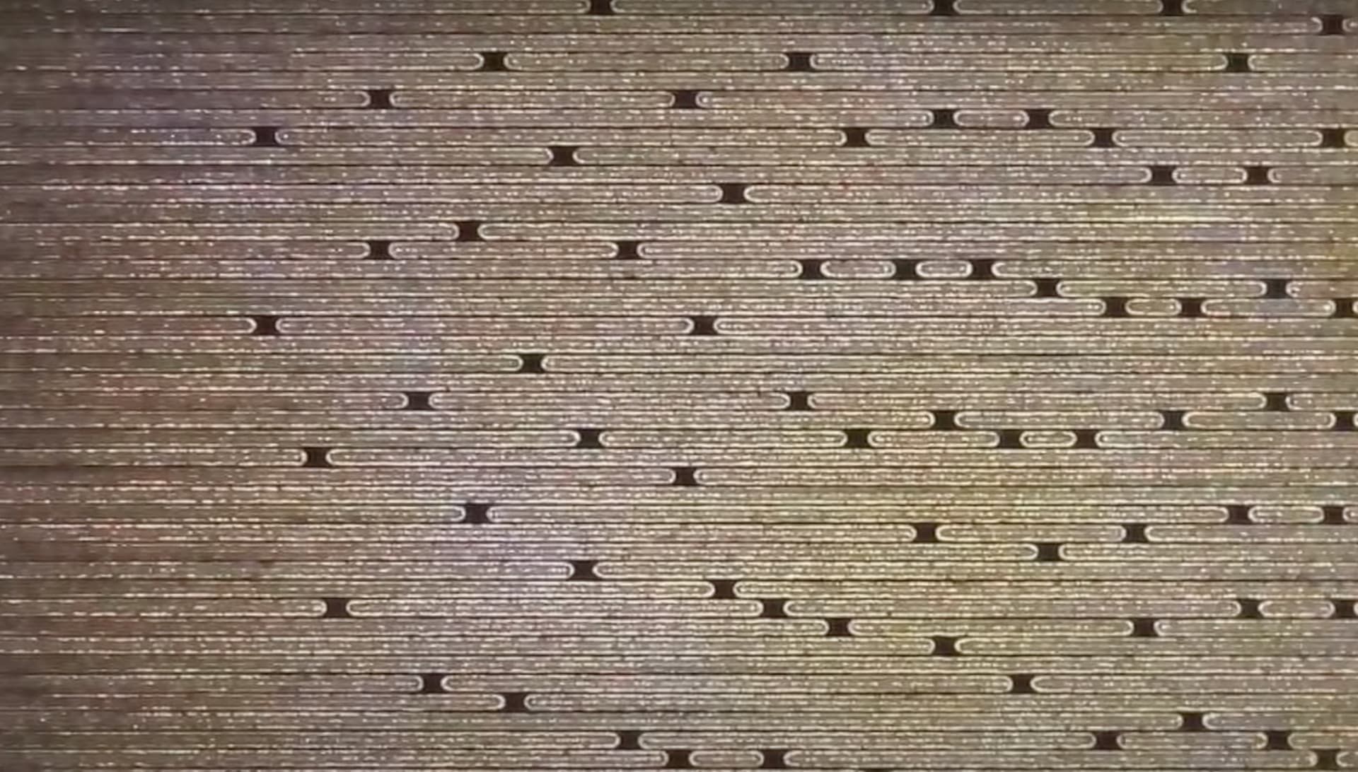
Hi Gentlemen. These are my latest results. Having read your suggestions Jack, I thought I would check everything. The laser tube was not secure in its mounts, so sorted that and ended up with better alignment from Tube to M1 anyway, it was always slightly high. Then a I recalibrated M1, M2 & M3. The first result is the is Gareth’s dot test run on card. The second is a grey scale test run at a line interval of 0.15mm.
Clearly the non secure tube was an issue. Using Gareth’s guidance would you say that a line interval of 0.15mm is the best resolution on this device? I’m thinking the dot size and therefore line interval is less than 0.2mm but more than 0.1. My only other thought is that the lines are defo not touching on the greyscale test, which would indicate slightly higher resolution would be available on the anodised alloy business cards. Also, do you think the burn marks are about right for a CO2 gantry laser? The diode Galvo seem far better and more consistent.
I don’t know who this is… So can’t really comment.
What line interval are you using here?
With the proper line interval it should be just touching… or you will have gaps in the scan lines.
My machine with a stock lens, 1.5", can do about 0.10mm line interval with the compound I can get at least 0.05mm or less…
You need to solve the Y wobble problem before you’ll have a good functional machine.
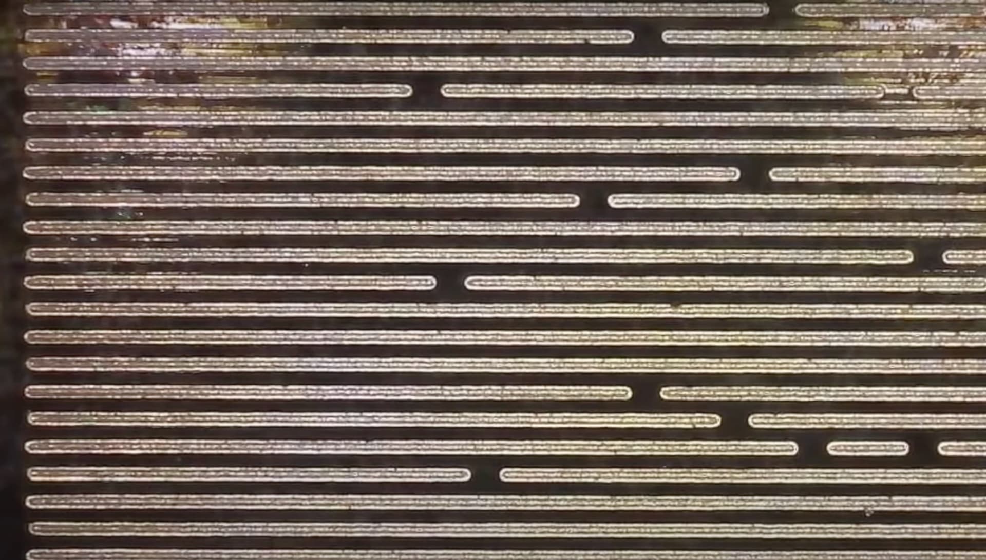
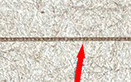
I circled a few lines that wobble, this should not happen… You can see it on all of the output you posted… it’s not straight.
Since it’s doing it where it should be going straight along the X axes, its going up/down… indicative of Y axes issue.
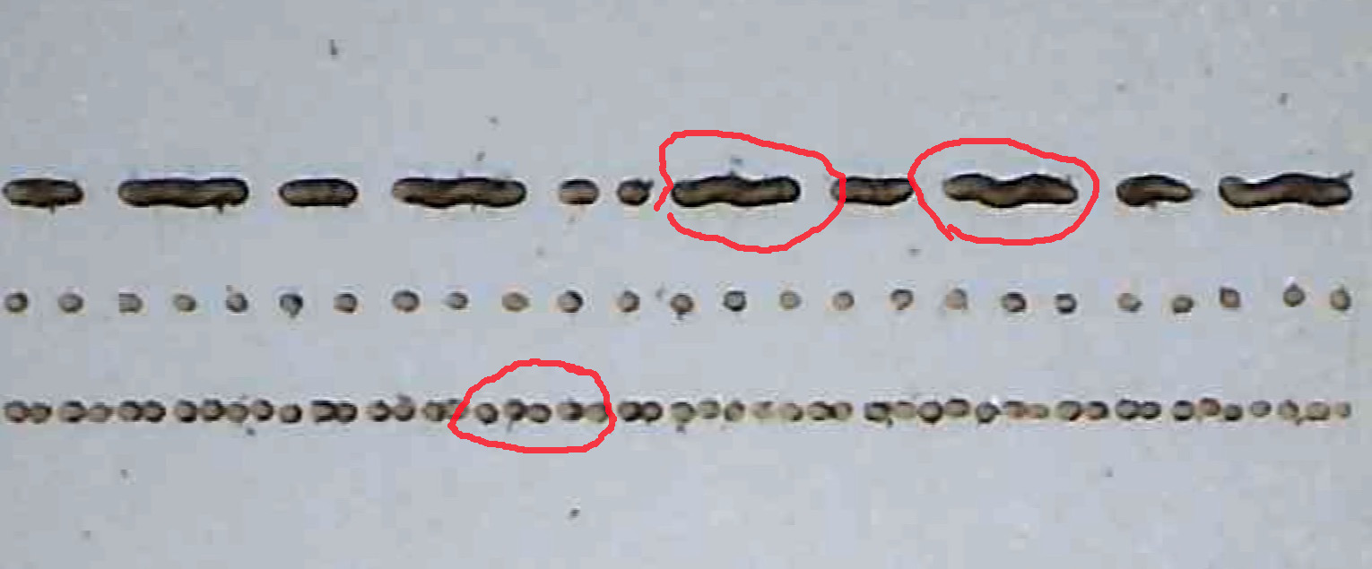
I would think this is evident of issues with the Y axes (assuming X is horizontal) being lose or incorrectly adjusted… It could be a grub screw coming lose or some other mechanical anomaly.
Better output… keep adjusting ![]()
![]()
Or a loose lens, as happened with somebody else in recent memory. You’d never notice anything along the X axis, but any motion in Y would produce those worms.
If it’s traveling in the X direction, I wouldn’t expect any wobbles in the Y direction…
Or is that what you are saying…?
![]()