I have a laser mounted to a CNC router. I have a dedicated A axis rotary that is oriented along the Y axis (wrapping X). I’m trying to figure out how to set up Lightburn to work with it. If I choose A axis in the rotary setup and create gcode to send to the controller (GRBL), only the A axis moves. The gantry stays in place. Is there a setting in Lightburn to let it know that the A axis is aligned along the Y axis? As I mentioned, I’m not using the Y axis motor to turn the rotary. I have a dedicated motor for it.
I’m new and am certainly missing something simple, but I couldn’t find it in the documentation or in this forum.
Thanks for your help!
A few questions please:
- In order to remove any ambiguity, can you provide a photo of the rotary as it’s oriented in the laser?
Is this to say that you get neither lateral or vertical movement on the gantry? So no movement at all?
Have you tried connecting the rotary to the Y-axis? If so, do you get different results?
- Can you take a simple design and prep everything for rotary burning, then go to File->Save gcode, save with .txt extension and upload the file here please?
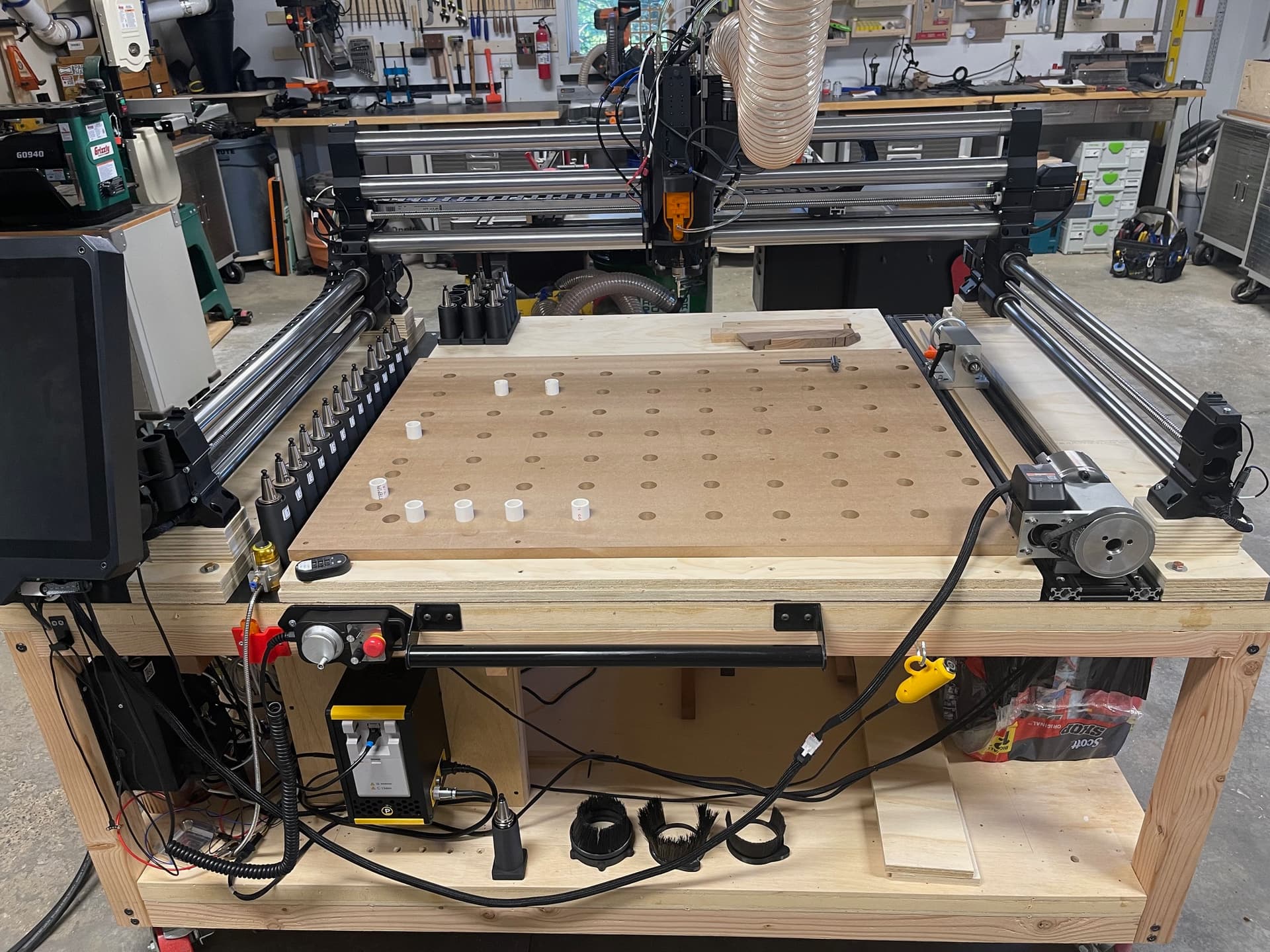
Here’s the machine from the front - Rotary on the right.
Here’s the gcode created:
Test.txt (270.5 KB)
There is very slight movement on the X axis (you can see that in the code), but primarily, the rotary (A axis) just swivels from side to side.
I can’t use the Y axis motor, when I wired the rotary, I used different connectors that I had on hand.
When I use the rotary for carving, I have to input the orientation of the axis into the CAM software (either Fusion 360 or Vectric VCarve) so that it knows which axis to move other than A and Z. I just don’t see that option in Lightburn. It has to be there, doesn’t it?
Maybe this:
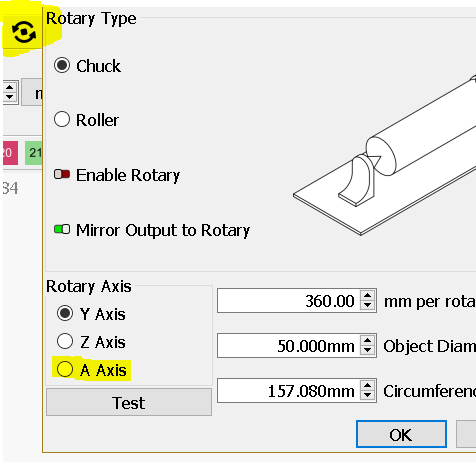
.
Nice and solid CNC machine.
Thanks. Yes, I had A axis selected already. The question is, how does the machine know what orientation the A axis is in? What if my rotary was oriented diagonally across the machine bed? Of course I wouldn’t do that, but there must be some way to set in Lightburn the orientation of the A axis.
The orientation is set by the operator according to instructions from the manufacturer.
Lightburn can make straight output or if your machine mirrors the engraving, Lightburn can be set to mirror the output for the engraving to be right.
Where do I set the orientation in Lightburn so that it knows to write gcode to move the laser back and forth along the Y axis as it is turning the A axis?
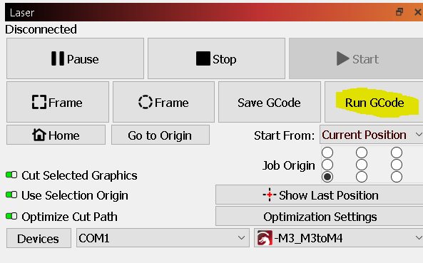
Why did you setup your laser in Lightburn as GRBL-M3 and not as GRBL?
I don’t believe LightBurn can support that orientation of rotary. Essentially, LightBurn assumes X travel across a rotary Y or A in the case of g-code machines.
Your configuration would require Y movement across a rotary A.
You might be able to hack a solution by setting up your design in a landscape configuration, exporting the gcode, then editing the gcode to swap all X movements for Y and all Y movements for A.
I was afraid of that. I’ll rant a little. That seems crazy to me. The parameters to generate that code would be simple to design in the software. Why would they limit it? I know that most people using a rotary have one that is portable, but if someone has an A axis, it’s probably not portable. Also, the documentation is lacking. This could be addressed if it’s the case. Ok. End of rant. Thanks for your help, I appreciate it.
I don’t know if it’s so much limited as it is more that alternatives are not common or prioritized. However, I’m speculating.
Typically scanning operations are much more efficient along the X axis since there’s much less mass that’s moving in comparison with moving the entire gantry.
I’d suggest putting in a feature request to raise awareness of the need.
Because that’s what the manufacturer of the laser indicated was correct.
Your motors are closed-loop?
When you want to use the chuck you move laser head to the right and scan in Y?
Don´t know if this gone work you have to try, swap X/Y check gcode and run a job.
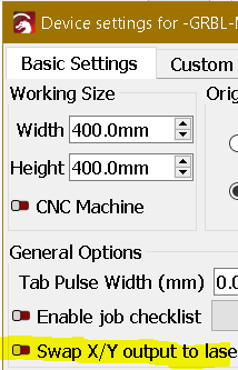
Yes, the motors are closed loop. I didn’t see that swap X/Y. I’ll give that a try. Thanks!
Upon swapping X/Y + A maybe you have to put your design along Y.
Out of curiosity what is your controller model?
Unfortunately, that didn’t work. I’m still only getting miniscule movements in Y. A axis (the rotary) just swivels back and forth.
The machine controller is a Masso G3.
Ok. Original configuration. Draw a simple shape along Y (+A) and post here.
If you edit your GCode with Notepad++ (free) by replacing X with Y and then run the code trough Lightburn does it works?
.
If the above works you could try creating a Custom Gcode with GRBL -M3 flavor (for now) device by clciking Devices > Create Manually
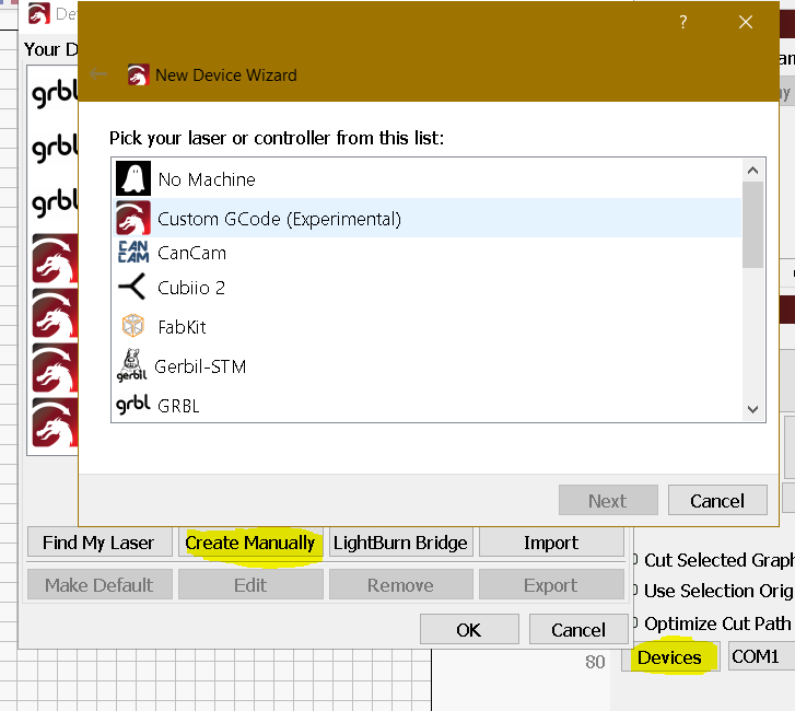
or other flavor that suits the output your laser needs, so Lightburn can output the correct GCode.
Report back with your conclusions.
I created a Swap X/Y device with the following shape:
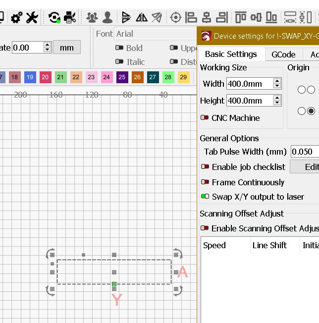
.
I enabled Rotary using A axis
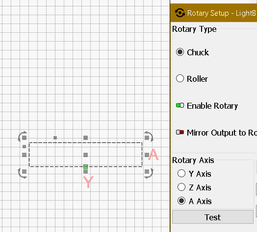
.
Output GCode:
; LightBurn 1.7.00
; GRBL device profile, current position
; Bounds: X-63.5 Y0 to X63.5 Y27
G00 G17 G40 G21 G54
G91
M4
; Cut @ 6000 mm/min, 20% power
M8
G0 Y63.5A0
; Layer VirtArray
G1 Y-127S200F6000
G1 A15.47F3437.75
G1 Y127F6000
G1 A-15.47F3437.75
M9
G1 S0
M5
; return to starting pos
G0 Y-63.5X0
M2
.
.
I believe is a starting point and maybe no need to swap X/Y and it´s possible you need to apply a ratio to your shapes dimensions.
I confirmed you have to Swap X/Y so the output is Y axis and A axis.
I tried swapping x and y. I’m not getting movement along y.
; LightBurn 1.6.03
; GRBL-M3 (1.1e or earlier) device profile, user origin
; Bounds: X606.51 Y272.58 to X660.48 Y295.82
;USER START SCRIPT
T111 M6
S0
M5
;USER START SCRIPT
G00 G17 G40 G20 G54
G90
G0 Y0 X0
G91
; Scan @ 1.969 in/sec, 50% power
M8
M5
G0 Y-1.515A-98.972
; Layer C01
M3
G1 A-8.058F118.14S0
G1 A-3.696F380.704S127.5
G1 A-8.058F118.14S0
G1 Y0.0033A-2.95
G1 A8.058
G1 A9.62F380.704S127.5
G1 A8.059F118.14S0
G1 Y0.0034A1.899
G1 A-8.058
G1 A-13.383F380.704S127.5
G1 A-8.058F118.14S0
G1 Y0.0033A-1.166
G1 A8.058
G1 A15.747F380.704S127.5
G1 A8.059F118.14S0
G1 Y0.0034A1.129
G1 A-8.058
G1 A-17.903F380.704S127.5
G1 A-8.058F118.14S0
G1 Y0.0033A-0.747
Obvious this may need fine tuning or even not work.
I have created a Custom GCode GRBL-M3 device in inches set to in/s.
A rotary test rectangle 5" x 2"
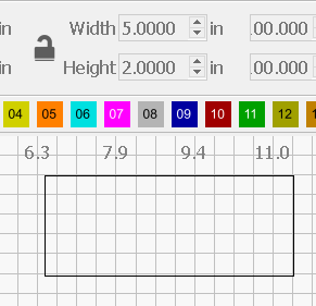
produces the following GCode:
;LightBurn
;Custom GCode device profile, current position
;Bounds: X-2.5 Y0 to X2.5 Y2
;USER START SCRIPT
T111 M6
S0
M5
;USER START SCRIPT
G00 G17 G40 G20;Restore imperial mode
G54
G91;Restore relative mode
M3
;Cut @ 1.969 in/sec, 50% power
M8
G0 Y2.5A0
M3
;Layer C00
G1 Y-5S127.5F118.14
G1 A3.0077F177.662
G1 Y5F118.14
G1 A-3.0077F177.662
M9
M5
;return to starting pos
G0 Y-2.5
M2
- 1.Draw a rectangle with 5" x 2" poste here the .lbrn2 file, enable rotary with A and post the output GCode.
- 2.Swap X/Y draw a rectangle with 5" x 2" poste here the .lbrn2 file, enable rotary with A and post the output GCode.
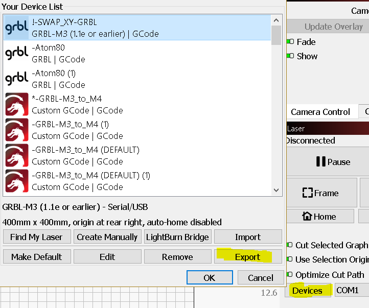
Also post your device .lbdev. by clicking Devices > select your device an then Export.