Hi, I’ve been struggling with a problem for quite some time, but now I decided to ask the professionals. I have a co2 laser 80 watts I use the light burn program. The problem is that I set x and y to cut them 100mm and I get it perfectly, Then comes the problem part of the grid 20mm x 20mm and there I already run away from the correct cut, Then I set it to cut my part exactly 20mm x 20mm and it goes from perfect, but then the detail I want to redo again 100mm x 100mm is again not accurate, the size has escaped. I can’t figure out where I am wrong or something is not set correctly, my colleagues do not have such a problem, set them the steps from the stepper and everything is fine. If anyone has a logical explanation, I’d appreciate your help
My machine is a red CO2 Chinese version with Ruida 644xs 80W.
I don’t use this option, I’ve read about it and what it does, but I’ve never turned it on. I check the machine for backlashes after each completed order, as well as the backlashes of the belts. The interesting thing is that after setting in the options of the controller for an accurate cut, it works great, but if I change the size of the new part, the accuracy starts to run away.
I will check every time to see if this option is turned on by itself, but this is exactly the calibration I do and set everything to be perfect by measuring 100mm x 100mm with an electronic caliper, I measure the cut made and it is up to 99.99. Then I try to cut a part 20mm x 20mm and a deviation of 20.5mm x 20.5mm is visible, I adjust it again with calibration to cut 20mm x 20mm with accuracy, then I run a part 100mm x 100mm and again we do not have a 100mm x 100mm cut. I don’t know what the reason is and it’s confusing my work a lot because I also work with a UV printer and I need precise cuts due to arrangement of figurines, etc.
The kerf should be about 0.15 mm, but that depends on the material, speed, and power. I just measured 0.6 mm for EVA foam sheets!
If you calibrate the axes to cut exactly 100 mm without taking the kerf into account, you have actually calibrated it to move 100.15 mm: an error of 0.15%. Similarly, calibrating exactly for 20 mm means it moved 20.15 mm, an error of 0.75%. In both cases, subsequent cuts will be too large and the error will increase proportional to the nominal length.
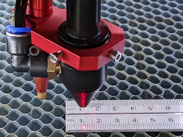
Rather than measuring a cut object to calibrate the axes, measure the distance moved on a machinist’s scale or the distance between pulsed points on a sheet of paper:
When you cut objects, increase their nominal size by the kerf, perhaps using the Offset tool, which then cuts the actual part to the correct size regardless of the length: the nominal size plus the kerf.
If you work with parts made on a different machine, you must calibrate both machines to the same standard and verify their agreement. For example, I found a mis-cut leadscrew in my 3018 gantry machine:
And printed shapes on paper can be completely wrong in both scale and shape:
Getting accurate results is a never-ending challenge!
I definitely didn’t make that clear. I’m using “kerf” in the machining sense as “the width of the cut” made by the tool, so the offset you’d add to the part would be half the kerf.
The kerf happens all around the part, so you get half of it on one side and half on the other; the waste material on the outside gets the other half all around. Overall, the part is then too small by one whole kerf width. If you enlarge the part using an offset of half the kerf, the part gets cut to the nominal size.
For the box you cut out, the tool path distance (measured width or length) loses -1/2 kerf to cut the first side and -1/2 kerf for the side that is parallel to it. The length or width of the resulting cut-out measures at the commanded distance minus 1 kerf width.
The hole in the parent material is 1 kerf width larger than the commanded distance of the tool path.
The kerf offset to make the part arrive at the designed dimensions is 1/2 the kerf width. The center of the cut-dot is moved out by its radius so it misses the work.