I would go on the assumption that my post 15 diagram is probably correct for A+ being black and A- being green, B+ as red and finally B- as blue.
Can you check that? You might have to ‘ohm’ out the wires or open the 4 pin connector cover.
Volt/ohm meters are very low cost… It would behoove you to just purchase one to have handy and learn to use it, which over time you will. It will be worth it’s weight in gold when you start using it.
I’m going to take my boss’s ohm meter home today if possible.
I figure you’re going to want me to hook up my rotary, and measure with the probes at one end on the stepper driver block on the laser and on the other end, measure with the other probe on that white 6 wire block to each of the 4 wires to see which one has continuity back to the stepper driver block?
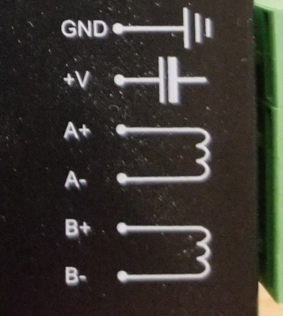
Follow the motor drivers output in the laser to the 4pin connector. Ensure that A+ is going to the A+ winding (color) of the 4 pin plug.
Keep in mind that when you look at the back of the connector, it’s pin out is flipped. Ensure you know which side of the connector things reference. Some of these have the pins numbered, some don’t…
I’d leave the rotary/connections alone until this is sorted out…
I’d use the colors described in the motor pdf as a guide for the phases. Follow A+ wire from your laser motor driver to which pin it uses on the connector then where it ends up through the connector.
If I’ve lost you, speak up… It would be nice if you understand what you are doing
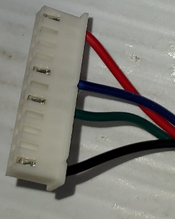
Ok, so dummying down for me, I put 1 probe on A+ on the stepper driver on the laser. I probe each pin on the aviator plug at the other end in my laser. So I’m basically identifying what wire on the stepper motor driver inside the laser, matches up with the pins on the aviator plug. The aviator plug is numbered 1 though 4 on the black plastic end that the wires are soldered into.
Then measure A-, B+, B- and so on…
At the end of this, I should know where A+, A-, B+, and B- ends at the aviator plug and to what pin numbers.
Of course, with an ohm meter, the machine needs to be powered off.
Personally, I’d plug the rotary pigtail into the Y axes without the motor. Use the ohm meter on the motor driver A+ and check the BLACK wire where it plugs into the motor. You can then check A- to see it it goes to the green wire… Similar with the B windings, B+ should go to RED and B- to Blue.
You’re just skipping the 4 pin connector, hoping it’s correct. If they ohm out to different colors then the 4 pin connector, motor side or laser side… would have to be modified.
set the dial nearest the Jaws for 2000 OHM ( it’s a Greek Letter Omega )
you’ll see a 1 on the far left of the screen or NC for Not Connected or No Continuity.
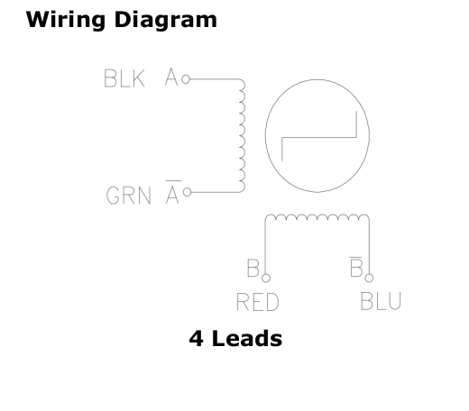
The wiring diagram Jack offered is really useful. The four motor wires are connected to the two coils inside the motor. The two coils aren’t connected to each other so each wire will have one partner. Once we know which pairs feed one coil or the other the motor can be Connected. If there’s an error and the motor doesn’t move reversing one pair of coil wires addresses it.
Stepper: A+ Brown ---- Red on the motor
Stepper: A- Black -----. Black on the motor
Stepper: B+ Yellow ---- Green on the motor
Stepper: B- Blue ----- Blue on the motor
Do an ohm meter check for continuity between A+ and A-… Need to do this on the motor side… It might be easier to either use the probes on the connector part if you can get to it. You might have to remove the connector on the motor and touch them with the probes.
I’m wanting continuity between the inputs to show it is either A+, A-, B+ or B- phases.
If you look here… Red + Blue are one phase and Black + Green are the other.
I threw a probe on A+ on the stepper driver in the laser, and touched the other probe to all 6 pins on the motor with the other end connected to the aviator port on the laser.
I also touched the probe to the 6 pin connector that attaches to the motor, and probed the motor.
If you can, take the cable out and try to match up from end to end. Sounds to me like there is at least 1 wire has a bad connection. Probably inside the aviator plug.
So as an example… Lets say I’m going to work with pair 1 & 3. The red / black wires.
Pick one of them, and see if either one tones with A+/A- or B+/B-
Correct?