A rotary attachment question. Warning: Newb

You have already told me to ‘toned’ the pair out… ? Are you saying follow the lines back…?


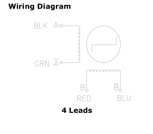
You can follow from the motor connector to the motor driver and see if it matches the posted schematic… I.E. does A+ (black) on the connector ‘tone’ with the motor driver A+? Do that with the other 3 wires…

Make sense?

:smile_cat:

yeah I think I got you.
:slight_smile:

I’ll let you know this afternoon. I usually get home around 12:30’s to 1:00

(Laser Stepper Driver A+ Brown Cable) tones to (Red Cable Motor side)
(Laser Stepper Driver A- Black Cable) tones to (Black Cable Motor side)
(Laser Stepper Driver B+ Yellow Cable) tones to (Green Cable Motor side)
(Laser Stepper Driver B- Blue Cable) tones to (Blue Cable Motor side)

Screenshot from 2023-01-22 12-49-35

What you have is a driver connection, motor (currently) and Correct (where it should be)

Driver Motor Correct
A+ Red Black
A- Black Green
B+ Green Red
B- Blue Blue

Follow?

:smile_cat:

So I should just basically pull out the wires in the nylon block, and switch them to the “correct” position noted here

Driver Motor Correct
A+ Red Black
A- Black Green
B+ Green Red
B- Blue Blue

Where RED is now, swap the black wire to that spot, and so on?
Do you know what they call that nylon block?

The correct place to do this is at the 4 pin connector… IMHO … the easiest place is probably the white motor connector.

You know how to find the pairs… whatever you find to be the path of least resistance.

These connectors release the pins pretty easily when you can press down the flange that locks it in place… Usually a sharp object…

Here a 6min video… if you haven’t…

Good luck

:smile_cat:

I know how to solder so I could do the 4 pin connector. I’ll probably have to go the soldering route.

Having said that. If I go the soldering route, do I need to swap out the wires shown above to the correct colors RED to Black, and so on on the white nylon block, or will just the soldering do the job.

Inquiring minds want to know :slight_smile:

Well for giggles, I swapped the two middle wires on the rotary motor wire in the nylon block. Same vibration. Going to put them back, and do some soldering on the aviator plug.

Your reference mode has me stressed… I can’t keep track of colors as they have no meaning except at the motor, via the documentation.

I have to have a bunch of windows open to relate to what you are saying.


In simple terms, if we depend on the documentation, which is all we have, of the motor there are certain colors to identify A+, A-, B+ and B-…

I could really care less about the colors… A+ out of the motor needs to get to A+ of the motor driver… same with the other three wires…

Once you change it, did you check with the ohm meter as a double check to see if they were going to the correct connections of the motor driver?

It’s easy to mis-wire this stuff, so if it doesn’t work, I’d double check that you modified the correct wires.

:smile_cat:

All is good. …i soldered the connector this afternoon like you suggested.
Now give me a paypal email addy or a btc wallet address.
I owe you!!!

Success is paid in full to me… pass on your knowledge to help others and we all profit :slight_smile:

Take care and have fun…

:smile_cat:

4 Likes

I’ll do my best. I’ll buy someone’s breakfast tomorrow on your behalf…

Thanks for all your time.

No perspiration… take care

:smile_cat:

1 Like

Well Done Jack!

Credit where credit is due. :hugs: :+1:

2 Likes

totally agree,well said.

1 Like

This topic was automatically closed 30 days after the last reply. New replies are no longer allowed.