A rotary attachment question. Warning: Newb

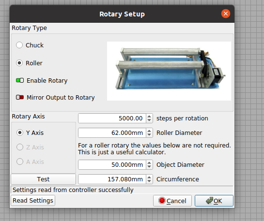
I have a Monport 55w Co2 laser. Just bought a 4 wheel rotary attachment for tumblers. I’ve gone into light burn and plugged in the wheel diameters and the diameter of a test piece “tumbler”. What I’m not sure about yet is the steps per rotation number to plug in. I’m trying to get that from China. Their US support tech doesn’t support accessories, just the laser.
I created a letter H with a fill setting. All I get is a small line being burned into my wooden test tumbler. The laser makes around 6 passes back and forth.
I’ve included a link to the image.
Do I have to “write” the configuration in light burn into the Ruida Controller for this to work? One of my steps per the US tech support tells me that when I’m done with any rotary job, I should disconnect the Y-Axis cable from the rotary, plug in the regular Y-axis cable, and press the reset button on the controller window on the laser.
What am I missing short of the steps per rotation?

https://drive.google.com/file/d/1jX2vzAwxpiKJIYdkIoGhFqLRejkQhX4d/view?usp=sharing

Configuring for a rotary should not be an issue.

I’m assuming you are using the Y axes… you didn’t say…

  1. find steps/rotation
    a. identify the switch settings
    b. translate from the motor driver placard
  2. steps/rotation is then computed based on a ratio.
    a. value entered is steps/rotation multiplied by the ratio which results in the steps/rotation of the wheel, which is what Lightburn needs to know.

This is the basic procedure.

Look up the settings on the devices placard…

For mine, there are 2000 steps/rotation of the motor itself.

The number used for steps/rotation that Lightburn needs is for the driving wheel.


In my case with a PiBurn rotary, there is a ratio of 2.5 to 1… the motor must turn 2.5 times to rotate the driving wheel once. This ratio should be made available to you from the manufacturer. You can compute it with diameters or counting teeth… much more simple and correct if you get if from the manufacturer… or in the rotaries manual…

2000 steps/rotation X 2.5 = 5000 steps/rotation in the Lightburn gui… like this

rotary-controller-settings

Pressing the ‘test’ button should rotate the driving wheel one complete turn and back…

Up to the driving wheel, the system is digital, so once set this should be accurate…

The only ‘analog’ part is the driving wheel itself… Mine is supposed to be 63mm and I measured it at 62… if you have to fudge it, this is the place.

Make sense?


When you enable the rotary it’s written to the Ruida. The only time you need to write to the Ruida configuration is changes made to the operating parameters.

I suggest you go to edit → machine settings. Then save to file the current configuration as a factory backup… it’s easy to forget what you’ve changed. I keep a configuration for a rotary and no rotary. I can just read from file and write them to the Ruida.

I have my acceleration set to single digits when engraving with vector art.

Good luck

:smile_cat:

1 Like

Thanks Jack for taking the time out to produce this info. Your right. It shouldn’t be hassle. Unfortunately after working with another end user of Monport lasers and attachments, we’ve determined it’s a wiring issue.

Previous to buying the monport 4-wheel attachment, I bought one from Jason, at Mansfield customs. It exhibited the same symptoms as Monport’s own rotary.

Even then, Jason mentioned that they [monport] must be doing something with the wiring. This brings me to today. When I hook up the rotary via the aviator plug, and turn on the laser, and get what you see here.

When I did some digging around yesterday, I “think” it’s a wiring problem “possibly”. They don’t match up, meaning A+, A-, B+, B-

I have an open ticket with them, but based on their poor performance in solving things, and communications, I may end up buying a table top laser with rotary, so I get some work done.

Here is my rotary having convulsions when the laser is turned on.

https://drive.google.com/file/d/1DNefLH3OwQOC4L8mixYpNDFCH9ZiiuYc/view?usp=share_link

1 Like

I have never wired a two phase motor with something like A- connected to one of the B connections… I would have to look into how the motor driver output is designed to see if you’d get your type of results … nice video, btw… :rofl:


The phases are clearly marked on all the motor drivers I’ve seen…

If you swap A/B then the motor goes the other direction… My PiBurn came where it ran backwards.


Suggest you follow the wires back to the connect then to the motor and see how they are wired… There’s no standard that I’ve ever seen…

Ensure they are wired, at least the phases. And the -/+

Does your motor driver have step settings like mine?

:smile_cat:

Hi there.

I found a diagram yesterday about the pins on the Aviator Plug.
https://drive.google.com/file/d/1Jm2P0YudVky1G_9FoYe_KiXTNOZGaZd8/view?usp=sharing

My y-axis aviator plug is:
Pin 1 - RED
Pin 2 - BLUE
Pin 3 - GREEN
Pin 4 - BLACK

I’m sure color really isn’t relevant on something like this, but it does match mine somewhat. The color scheme they used on the stepper motor block is totally different.

Rotary Attachment plugs:
https://drive.google.com/file/d/14DZiU23uwYHEAjG6qcVHvnNOA-ktByj1/view?usp=share_link

Stepper Driver Block
https://drive.google.com/file/d/15CueRIEAYFUBNCeODC3Lfr80IIRFz_Qs/view?usp=sharing

Let me throw this out there. According to the fellow I spoke with yesterday. A monport user. We’re thinking wiring scheme not matching.

Throwing this out there. We believe the bottom stepper driver block is for my Y-Axis. If I flip one of the dip switches based on how many steps he uses, is there any danger of blowing something on my stepper driver block?

I don’t want to dig myself a hole, since there is NO US support for this.

Thoughts?

Absolutely, forget the colors, follow the wire…


Again, forget the colors, follow the wires to the Ruida and you’ll know which is which. The only real good use of color is it makes following the wires easier.

Is there any indicators on your motor for A+, A-, B+, B- ?

You should wire them up with A+ going to one of the phase A+. I would guess they would conflict if you swapped them, since it would drive it the opposite direction.

:smile_cat:

I’ll see if I can follow the wires.

No wires to see on the motor of the rotary.

If you have an ohm meter you can at least get the pairs…

There must be some kind of information on the motors… Do the wires to the motor have a connector or do they run directly into the motor… Maybe we can find the connector pinout.

:smile_cat:

The wires plug directly into the motor via the white piece shown here.

https://drive.google.com/file/d/14DZiU23uwYHEAjG6qcVHvnNOA-ktByj1/view

The other end is obviously the aviator plug.
The motor has no markings on it. I’ll post an image of the motor that is housed in an aluminum box.

Motor Pic 1
https://drive.google.com/file/d/1B48chekNBCx6ukX-pt29YajYOm1WEAma/view?usp=sharing

Motor Pic 2
https://drive.google.com/file/d/1_lYA4SkjYmeUha7r892twAaOj0H8Usfi/view?usp=sharing

Motor Pic 3
https://drive.google.com/file/d/1AaLXsy8xX2fpTiVHlRz0SyooX0GIoC2K/view?usp=sharing

Actually it does

It doesn’t say a thing about there even being a connector…


Do you have a volt/ohm meter?

:smile_cat:

Good am Mr.Jack.
Na, I don’t have a meter, but my buddy that is the mait. guy where I work 4 to 12 does. Not a problem getting my hands on one. But even then, I wouldn’t know how to use it…

LOL

We’ll hold your hand… if I need to, I can ring you up… ?

Did you download the pdf I posted? It’s the document on your motor.

:smile_cat:

Give me a call now if you just want to give me an over view of your thinking. I’m just soaking a Charcuterie board…

Going to be out of pocket for an hour or so. Visiting the in-laws.
Thankx

This pdf has more information… I removed the previous one.

This one at least has a visible connector but it has a color scheme that might help us with your connector…

See if the wires at the motor connector end could be associated with the proper field windings. I can’t really determine the wire colors from the pigtail you supplied.

Screenshot from 2023-01-22 12-49-35

Hope you had fun at the in-laws…

:smile_cat:

In law visit is always a piece of cake. I had to drive them in their new car they bought yesterday. He can’t drive anymore, so they wanted to go down the road in it.
Dealer delivered it to them yesterday.

BTW, my motor is:
57BYGH56H-A-23D

I have no clue about the wiring diagram provide above… :slight_smile:
I’m a network admin and wood turning hobbyist

:slight_smile:

I was looking at your connector wire colors… That may match with the last post diagram… Can you check?

It’s the one with the 4 pin going to the white connector… I cut the picture out but I have some issue that sometimes the drag and drop doesn’t work.


Just upgraded to 22.04 Ubuntu… I wish I would have waited…

:smile_cat:

Hello there.
When i get home tomorrow afternoon I’ll get everything pulled apart so i can identify everything clearly for you…
Thanks for everything…

Re-started Firefox and it seems to be working…

Screenshot from 2023-01-22 16-04-55

Are these red, blue, green and black? That would match with the posted pdf and diagram of the motors phases.

:smile_cat:

20230112_145153