Absolute coordinates not working as expected with jig

I am trying to set up a jig so that I can cut from both sides of my piece in order to cut thicker and/or more difficult materials like MDF. I’m trying to follow what this fellow did, but with different software, as he didn’t have Lightburn. Here is his video on YouTube. How to cut through double the thickness. Using 50W Chinese Laser Cutter - YouTube

I have a very similar Chinese machine, an Omtech 55W laser with a Ruida controller.

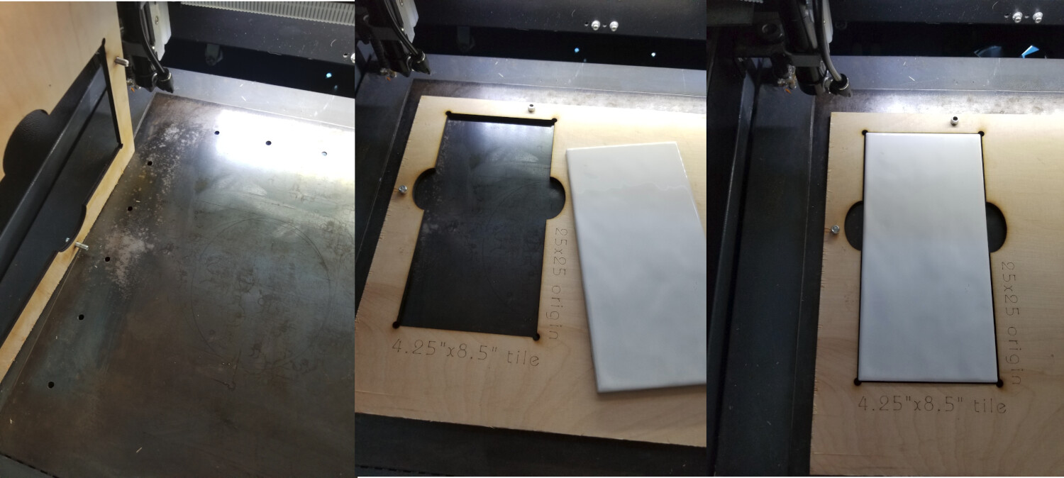
Here’s what’s happening; no matter if I use absolute coordinates, user, or current position I cannot replicate what he has done. I built a large L shape, roughly, then bolted that to the machine and had it cut out the x and y legs so that I have a square with one leg on the extreme left and the other at the extreme top, like his machine, then made the smaller jig that references on it.

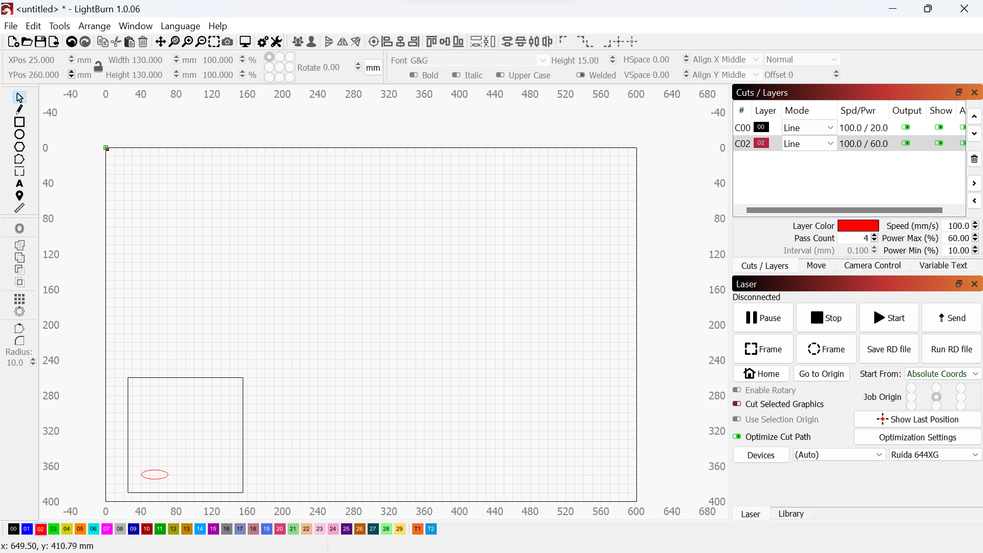
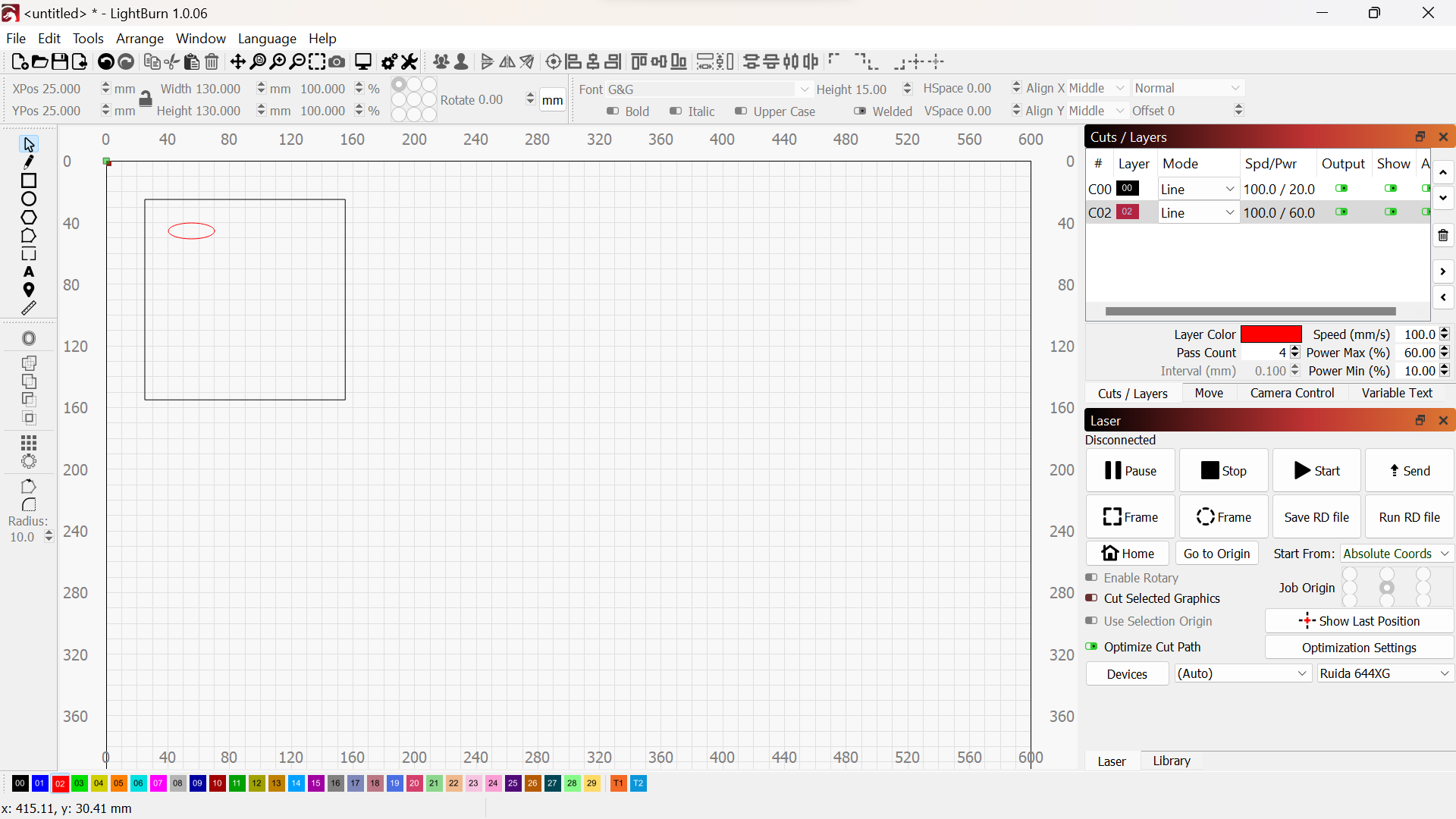
OK, so now I want to cut something from both sides, say a simple oval, it doesn’t matter. I placed the oval to be cut in a square that doesn’t cut, but that I can use to place the drawing in the upper left corner at 0,0. I then cut one side of the material, with no problem. Now comes the hard part for me! No matter what I do, I can’t get the laser to properly recognize that I have dropped the drawing down 255mm (the inside of my jig) and flipped the drawing. The laser wants to cut too far to the left and too far down or it just wants to cut in the old place depending on what coordinate system I use, even though the drawing is now showing that it is 255 down the Y axis. The Absolute choice just recuts in the same spot as the first cut.

I know this makes no sense without watching the video, so please do that. Also realize that the drawing itself makes no difference as the machine does the first cut just fine, regardless. I hope that somebody tries something similar. You don’t have to build the jig, just try and follow the steps he goes through, only in Lightburn.

I’m still using version 1.0.06 of Lightburn if that makes any difference.

Thanks!

You should use Absolute Coords for both sides of the cut.

When using Absolute Coords the design should burn to the matching location on your bed as it’s located on your workspace in LightBurn. This is irrespective of when trying to flip the material. A shape positioned at 10,10 on your workspace will always burn at the corresponding 10,10 location on your bed. Similarly, a shape positioned at 10,50 on your workspace will always burn at the corresponding 10,50 location on your bed.

Thank you, that is what is happening. How do I flip, move to the bottom part of the jig and have Lightburn follow that?

I’m trying to understand in what way the behavior is somehow different on the flipped side of the burn? Are you saying somehow that the burn is occurring in an unpredictable location but only on the flipped side?

If so, can you do this:

  1. Take a full screenshot of LightBurn with the front side setup. Please save and upload the .lbrn file here also.
  2. Take a full screenshot of LightBurn with the reverse side setup. Again, please save and upload the .lbrn file.

Yes, that is what I thought, but it doesn’t do that. I got it to move down in the Y axis now, but not to the specified location. Do I have to change which corner it uses in the 9 dots in the top menu or what?

I think you are complicating the issue… First, if the board isn’t square to the sides/ends it won’t line up, so flipping down to another position doesn’t ensure it will line up…

Think what would happen if it was a long trapezoid… when you flipped it, the square end might be on, but as the laser moves away from that end it will not line up to the original.

Another issue, is things with sharp corners don’t work as well as having a hole in the corner to make up for this…

This is one of my jigs for porcelain tile… granted I’m not doing both sides, but the alignment game is the same… Notice the circle cutouts in the corners to allow for the point of the tile… ensuring it doesn’t effect alignment.

I have about three of these … doesn’t appear that they are really the stated size, or at least not very close… One manufacturer tile won’t necessarily fit in the hole for another… kind of a bummer.


What you are referring is the job origin… if you run absolute coordinates, there is no job origin other than 0, 0

If you use another start from value, would need to change the job origin in the laser window…

image

If you want to go ahead with his instructions… use absolute coordinates for both halves. Move the position of the job to the exact location of the position of the flipped piece. Where ever it is on the workspace it will be placed for the laser. You can enter these manually at the top left…


IMHO, I think that’s a lot of work… I’ve done doubled sided pcb’s, so I’m not ignorant of the process.

I’d set it up to align by just flipping the object in the same place… Seems more logical as you are depending on it being mirrored… not to mention there isn’t any math to get hosed up…

Does any of this make sense? :pray:

Here is one of my template files. It is all the alignment and material holes when making the jig itself…

I keep this, write protected so I can import it, delete what I don’t need. If need be, just add the art in the circles… If I have to cut another one, I can do so…

4-inch-round-X6-pattern-locked.lbrn2 (82.2 KB)

:smile_cat:

1 Like

It does make sense, thanks. I will go back and try to simplify by flipping the ‘tile’ in the same spot. That makes everything easier and my tools can turn out quite accurate squares, so perhaps I’m trying to fix a problem that rally doesn’t exist in the first place.

Simplify, simplify!

Thanks!

KISS principle… keep it simple stupid

Good luck

:smile_cat:

if you post screenshots of LightBurn during front and back side burns it should be straightforward to determine what’s going on.

LB test 2.lbrn2 (8.3 KB)
LB test.lbrn2 (8.3 KB)


I see I made an error in this file and set up. The black line should be set to ‘No Output’ as it just represents the size of my workpiece. It really doesn’t make any diffence as it would just ‘cut’ what has already been cut.

Great advice!

The fundamental setup seems okay.

So to confirm, you’re saying the jig that you were using was positioned such that top-left corner was exactly at the 25,25 mark, and then had another horizontal component at coordinate 25,390? So the overall height of the internal portion of the jig was 365mm?

That is why a tool layer is used. Just to use as a reference… you have T1 and T2 on the right of the selectable layer/color…

:smile_cat:

Yes, exactly.

Yes, I use those sometimes, at other times I want to toggle ‘Cut’ or whatever, on and off and the ‘No output’ does that, but thanks for the tip.

In this case there’s something fundamentally wrong with your machine setup.

Does your laser burn dimensionally accurate parts? Meaning 100mm square is 100mm square when burned and measured?

How have you cut the jig? Was that measured by hand or was that done by burning from LightBurn?

Yes, 100x100 mm squares are cut accurately. Both jigs were cut with the laser so that they would up square according to the machine.

Did you save the designs for the jigs? Can you upload them?

Sorry, no, they were just quickie cuts, not woth saving. I can reproduce them if you’d like.