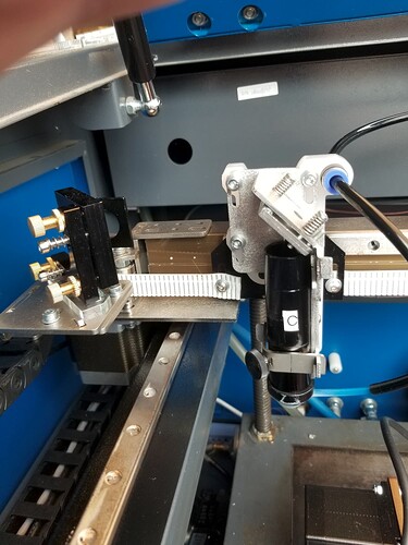
So Last year decided to build a new frame larger bed for my 100w CO2. Purchased complete gantry having the laser tube ride just behind the X axis …
Anyway this gantry came with new mirror holders and a head. Looks very similar to the Cloudray E Series (extended head).
There is only 1 spot in which you screw down the focus lens (top of the adjustable tube). The tube has a series of numbers (mm) on the side of that tube, Starting at 90mm at the top down to 10mm just above where the nozzle screws into that tube.
For the life of me I can’t figure out how to set this head and make matters more complicated, I have an adjustable bed with a Auto-Focus switch.
I have looked everywhere online for instructions on how to set such a combination of head with different lens combine with a movable z axis.
So I hope someone here can shed some light on this or point me to some instructions …
Possibility to adjust the nozzle itself with the lens, is not used when you use the autofocus function on the Z axis, I want to arite it all the way to the top.
Your focus is then “only” determined by your bed height/autofocus.
If you do not have autofocus, you use the adjustment option for focusing. The scale itself should probably be understood as a guideline for different lenses.
Hey thanks Bernd
The more I’m looking at this … The scale actually doesn’t do anything at all, The lens in the adjustable tube is in a fixed position, moving the tube up or down will not change the focal point of the laser it will remain the same distance from the lens position. Having said that … I can not use any other lens apart from a 4" (101mm) lens … because where the lens screws into the tube is 118mm from the opening of the cutting nozzle.
It is not quite right, if the lens is mounted in the lower part of the adjustable tube, you change the distance from the lens to the material surface by raising or lowering it.
IMHO and I’m a bit biased… I’d toss that head and replace it with something like the Russ Sadler design… One of the major failures of this type of assembly is that there is no Z axes adjustment…
This is his design on my machine… no drag chain… removing about 3/4 of the mass on that axes. Acceleration now set to 45,000mm/s^2 and will run 1650mm/s… The payoff is it drastically reduces overscan…
Here is the design if you wish to build one…
Most of these don’t really have the simple adjustments that make and alignment quick and easy…
My m2 mirror could not be adjusted in the Y direction. Necessary to move the beam impact point in the Y direction of m3.
Are you dragging that 100W tube around on the Y axes?
Good luck…
![]()
This topic was automatically closed 30 days after the last reply. New replies are no longer allowed.

