Stick tape over the holes and hold them over the nozzle. It will self center on most nozzles. You have 4 shots with one piece of tape…
I’d be happy to know what he’s forgotten…
I have a number of his parts in my machine, so we’ve had some email discussions. He even offered to get on the phone to help me out. You can tell he really enjoys these machines and their people.
If you watch one of his videos and have a question you can write him and ask. Every time I had an issue I got a couple of pages back in clarification. More than once a ‘new’ design he drew up to fix my problem. Usually a dxf file I could cut from acrylic.
Forgive me for being slow on the uptake …
I don’t understand how the beam checker tool would improve on the tape over the nozzle exit test.
Thinking Russ would have done a video … is how I ended up watching 3 other of his videos. instead.
The holes are the nozzle outline and the ‘burn’ will be relative to the center of the hole. 1 piece of tape to get 4 shots and you don’t have to stick it to the nozzle and it’s easy to tell where the beam comes out…
It is a bit more simple to use and read than sticking it on the nozzle.
THX Jack
Russ probably details how to use in a video … if you happen to remember which video to look for.
He has 227 videos to choose from.
I understand what your saying for how to use but I don’t understand how it could be accurate enough to dial in the beam center.
If there is any variation with how it’s held to the nozzle it could cause confusion when adjusting the mirror.
Again … THX for posting.
Just one more note, when someone of you is installing the printed air assist from Trek2120. Please note that the lower part of the Laser is not really flat which might result in air leaking out between the plastic part and the laser housing. You might want to add some sealant on the first ring of aluminium surrounding the lens and then screw it down. I used some 2 components modelling clay. works like a charm.
Good point! I used a piece of Gorilla Mounting Putty. I rolled out a piece with my fingers until it was about 3mm thick, then put it inside the bottom of the mount so that when I installed it, I could feel it seal.
Thanks for the great nozzle design, definitely the one i like most from those i have found so far.
having a bit of trouble finding the 3D printer nozzle for it, i found Prusa MK3 but i guess that’s not the one since MK4 aren’t released yet
Marcus, very appreciated for the info you share! I have 10W, 20W optical power blue laser head on hand, 40W blue laser head will be available in 2 weeks also. I will try Φ3.0mm and Φ2.0mm metal air nozzle to test the effect, and I will check the calculator with formulae also.That’s interesting!
I have not read the entire thread so please forgive.
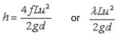
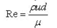
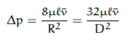
You could use a moody chart, and find the friction factor of the 3d printed material, then use it to help find head loss, pressure drop, and Reynolds number. this way you can find the optimum diamter for the hole.
these should be enough to find it all. I just did a similar homework problem for fluid dynamics class this week.
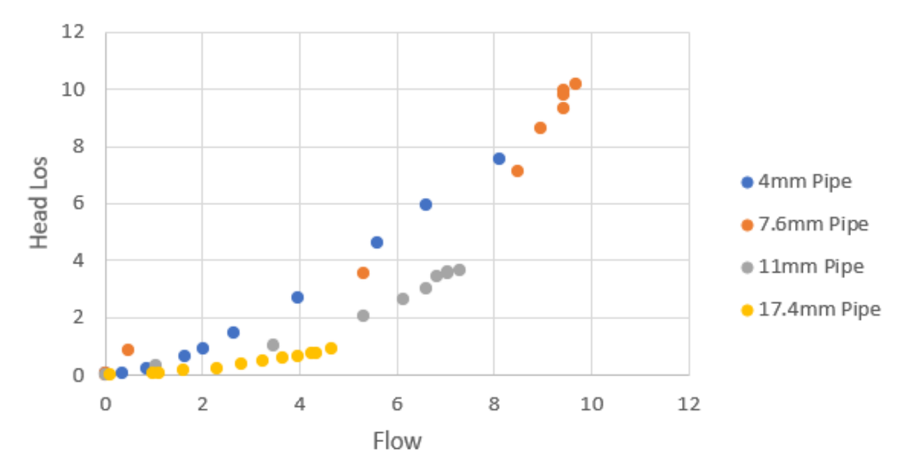
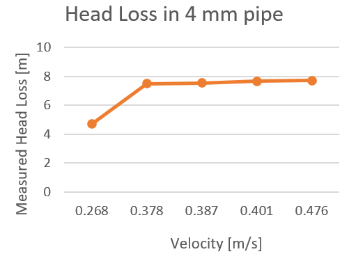
friction factor affects how fast the flow will develop, even with a very very low friction coefficient. As you increase diameter, the pressure will drop but flow can increase. there is a point where it is balanced, a transition point. usually between a Reynolds number of 2000 to 4000.
The graph below is one i made for sizes of pipes. this is head vs flow.