I am just wondering while looking at this the difference between the two cuts with the different nozzles the first cut looks like their was no presence of air assist at all.
The other point here is why high end company’s like Precitec, do not adopt this, the R&D and cost of their heads an nozzles that have a dual purpose, tracking and air assist, are very close to the surface due to the tracing ability and very direct, into the cut path.
I would appear that the need for laminar flow is more needed with the nozzle being so far away from the surface rather than forcing the air stream into the cut. to instantly remove or push the debris straight through and out under the cut…
In short making a meal out of a problem that could easily be solved by keeping the nozzle close as possible to the work surface and being precise, and push the debris away as fast as possible rather than a gaping hole for an air assist nozzle. and if as in many lasers the ultimate aim is single pass and push the air /gas so no debris is remaining on the surface.
Believe me when using Co2 lasers and cutting different materials, the smaller the outlet the less gas would be needed and oxygen and other gases like nitrogen for St/st etc the gas bill would be a pure waste , and the same nozzles are used just the gas selected changes.
To compare water jet cutting to laser cutting with nozzle and laminar flow, is strange as water jet cutting is extreme pressure and carries a substrate for abrasion.
I can not see the point of it when close and precise would just do the job without all the faff.
The idea of air is not just for clearance, it also makes sure the particles are reduced to the minimum but fast and quickly, and precision forcing the ignition of the combustable material and blowing it though would be the best solution.
seems like a lot of hot air !
Nervous System has been around since 2007 and has been doing some great work.
Most of their work is coding / software related not machine design.
The laser cutting machine being used wasn’t working as perhaps as well as another brand might.
It does appear a small change to the laser cutter they own made a big difference in cutting results.
Clever thinking rules the day.
The shape of the original Trotec nozzle looks to be designed for convince of manufacture rather than quality of air flow.
From the picture shown in the blog the transitions in the shape appear to be abrupt which surly creates turbulence as the air exists the nozzle.
Laminar flow abhors abrupt transitions.
Bravo to Nervous System for sharing the knowledge.
Well , all i can say to that is, when a laser machine in a production environment is running 24/7 the cost of a nozzle for as you say ease of manufacture, would not be an issue if it produced an improvement in productivity, reliability consistency and quality.
But the cost of the huge tanks of gasses would, perspective, a nozzle lasts for months if not years, so off set that against a full tanker delivery of oxygen 2-3 times a week, if there was a performance gain and a cost saving on the consumables, I am certain the cost of a more complex nozzle to manufacture, considering the size and outlay, and assured reliability to make such an investment, and running H rate, the additional cost of a nozzle if proven to be a benefit, is or would be of no concern. But each to their own beliefs.
Paul
My sense is, the average patron of this forum is a DIY hobbyist tinkering in the home shop with a fairly low cost, low power laser machine.
Most of this forum users are cutting thin woods, plastics, cardboard, paper not metals.
27/7 industrial machine forums reside elsewhere.
The smallest of the Trotec brand of laser machines start at $11,000 so would be less likely to be a hobbyist machine.
Their largest machine is 400 watts which would be barely able to cut thin-ish metal even with the help of high pressure pure oxygen or nitrogen.
Oxygen cutting pressures can range from 100 to 400 pounds per square inch (PSI), and consumption can be from 100 to 4,000 standard cubic feet per hour (SCFH).
Nitrogen cutting pressures are typically 300 to 500 PSI, and consumption can be from 1,000 to 6,000 SCFH.
My intent with including the link to Nervous System nozzle was to illustrate how paying attention to nozzle shape can improve cut results.
At a much lower buy-in then going through the trouble of switching to high pressure pure oxygen or nitrogen.
Steve
Is possibile for you to share the stl?
You totally miss the point that having a nozzle close to the work plane and especially when cutting, the operation is drill and move the aim is to blast the debris through the material and the diameter of the hole is kept small but large enough to compensate for direction changes and the deflection of the cut at is passes through the material, i do get your point . my explanation of gasses your pulling at strings, and i fully appreciate the hobbyist will not be using defined gasses, it was to illustrate the cost of efficiency, but again you missed the point. no matter the power or size or cost of a laser the principles are the same. be it a yag or fiber, diode or Co2 , its about clearing the debris and if on a cutting cycle the closer the nozzle the more efficient the cut it will assist.
take a look at examples of lasers cutting look at the distance from the wok surface the nozzle is, understand how air assist really works, by aiding destruction of the particles being pushed through the cut and the angle of deflection as the beam travels.
I do see their ideology of laminar flow , but as i said previously a comparison to water jet cutting is not even the same sport. I get their are benefits in some cases of laminar flow, but i would say that this is more down to the nozzle having to have a larger gap between it an the material, but after working with many different materials, including combustable ones, the advantage has always been keep the nozzle close when cutting,
I have never in all my years running lasers never seen a nozzle more than 2-3 mm from the surface and the aim was always the only Debris that should be present on the material surface is from the drill cycle.
The only advantage I can see from laminar flow would be if several passes are needed to cut through so to reduce cut path scorching or carbon impregnation to the edge of the cut path , for efficient and even lift of the expelled debris.
I really do get what they are doing , i just think they are providing a solution to a problem that could easily be avoided by other means.
and you would not use any gasses on wood, air is quite sufficient.
In short do you know if they even tried using a nozzle say 1.5 mm from the work plane with a single cut and just making the nozzle diameter small enough or just large enough , to allow for deflection to compensate when the direction of the cut changes.
I really am not putting down the solution they have made, but just from experience thinking it’s a solution to an issue that could be attacked by tuning height and pressure without all the faff, even it that means allowing for material flatness on the work surface.
Simple is usually more reliable.
Just because i refer to industrial applications does no negate the principles, a combustion engine works on the same principles, be it in a super car or the daily run around !
that said of course when engraving the distance of nozzle to surface would need to be greater , but they are cutting a combustable material and it is about forcing the debris and reducing the debris particle size as its pushed through the material so the laser can ignite the material, and clear it before the direct contact of the beam can scorch the surface by contact before the path it creates allows it to avoid contact.
When you see high powered lasers cutting at speeds of 20+ meters a minute and the issues low pressure and direction changes can cause on curves and corners, the picture of how the deflection of beam to it having a pre cleared path is obvious and 90% of the time due to low pressure or height of nozzle deviation to work plane.
Wood is not so easy, as an easily marked by carbon debris finding it way back to surface and being impregnated on the edge of the cut path, or the laser directly applying its energy to allow ignition to the material, the aim is to not allow the laser to touch the material, but to be close enough to provide ignition and assist the combustion pushing it through the material. wood has a resin content, you really do not want that heated goup hanging around in a cut path, it needs to be carbonised and cleared through the material and the edges of the material cooled as the beam passes by where it has been destroyed in front of the beam.
But like i said i’m not criticising what hey have achieved, I just believe there are far easier solutions to a common problem. I do believe that what they have made would be more beneficial to surface engraving for even dispersal and debris lifting to allow it to settle rather than being driven into the material causing the appearance of flash!
And wish them well. and the greatest success, their designs look creative an innovative.
The Nervous System design incorporates a flow straightener concept similar to turning vanes and /or the honeycomb grill that straightens the fan flow in a wind tunnel.
Turbulence at the nozzle exist will induce burning on the top of the material.
Fume extraction is also key to improved cuts.
Proper fume extraction will pull the fumes down and away from the nozzle and optics.
Fume extraction also creates a material clamping system.
A standard shop procedure was to choke the entire bed before cutting.
Once the material to be cut is placed on the machine, the left over open space on the bed is filled in with butcher paper.
With the bed choked fully the fume extraction system should be pulling the material down with 4 ~ 6 inches of vacuum pressure.
The vacuum holds the material firmly in place and also accelerates the air speed through the kerf (cut width) which greatly helps to improve cut quality.
A test Epilog laser suggests to verify enough fume extraction flow is :
With the lid closed place a sheet of standard paper vertical on the front grill, if the suction holds it in place there is enough vacuum pressure.
If it falls then fan speed or more choking needs to be done.
Hope that helps
Steve
So now its a transfer from bicycles as well as water jet cutting, but never will you look at the millions of pounds of development made by industrial manufactures, because is does
not suit what is a defence rather than a discussion or any inquisitive, blinkered reasoning.
I am sorry you feel like i am attacking what your doing, but making you defensive is not my intention. so as i have previously said Good luck with your route to solve the problem.
You obviously have neglected to actually understand how a laser passes through material and chose to not even make a comment on how, I have explained the cut principles, and have to mention now the cycling industries to unnecessarily defend with you superb design capabilities, i do hope you had no problems when you put the machine in a wind tunnel to expose the dynamics and velocity with high speed cameras and air die and the electron microscope used to film the cut in process. and now a vacuum chamber as well Wow.
I am done this is not a discussion , but just seem like any attempt will be made to not even consider established Known practises, to sell a 3D printed product.
But I guess the tour de France would have more useful input.
Signing off, you win your so fantastic I am in ore of your expertise i am but a mere microbe in your field of laser cutting technology and understanding!
But then no sale or can be made from known principles.
Sorry i will not respond with my full CV to back up what i am just trying to pass on as what i thought maybe useful information, but 40+ years in design production tooling in commercial rapid prototyping and high Volume automotive production, as well as Aerospace, would be too long to list. but i have to admit, i never did get into pedal cycles , just A380’s and mere low tech products like that!
Good day good luck!
Paul
Please understand, the nozzle information Nervous System provided was free for all to use.
Being the shop manager also included setting up the testing and measurement systems.
I’m fairly competent with CAD software modeling including flow and stress analytics.
Nervous System nozzle makes sense to me.
Here’s one of the projects I was involved in.
Pulling power from the sky movie
Cheers
Steve
You are all great people. But let’s Focus on the Air Nozzle. I found this here on thingiverse: Twotrees Totem S Air Assist, no glue, no screws by DrSchaumi - Thingiverse
It seems to obstruct the Red Cross laser, which I use to trace my work before Engraving or cutting.
Never printed it but What do you think of it? is it worth printing it? or altering it? Best Regards Patrick
Yes, clipping the laser with the nozzle is a slight concern. That’s a good idea, I could turn up a metal end so that’s definitely worth thinking about. I have been considering coating the inside of the smaller end of the nozzle either by electroless plating or another process I’ve rediscovered recently - chemical deposition of silver. However, the kits I’ve found so far for silver coating are prohibitively expensive. I remember silvering the inside of a test tube in chemistry class far too many years ago!. I might look into the chemistry and see if I can get it to work. One concern I have is that the laser might reflect off of the metallic surface and cause spurious marking of the material I’m working on.
I’ve modelled the laser ‘cone’ so I can see what clearance I’ve got. Obviously nozzle exit diameter is a compromise between air consumption and allowing enough clearance for misalignment. I’m lucky enough to have a Formlabs Form 2 SLA printer so the printed part is pretty true to the CAD model. Most of the materials are more akin to a thermoset rather than a thermoplastic so it doesn’t melt as such, it just decomposes. Obviously this will affect the shape of the airstream exiting the nozzle but I don’t consider this a significant issue in this application.
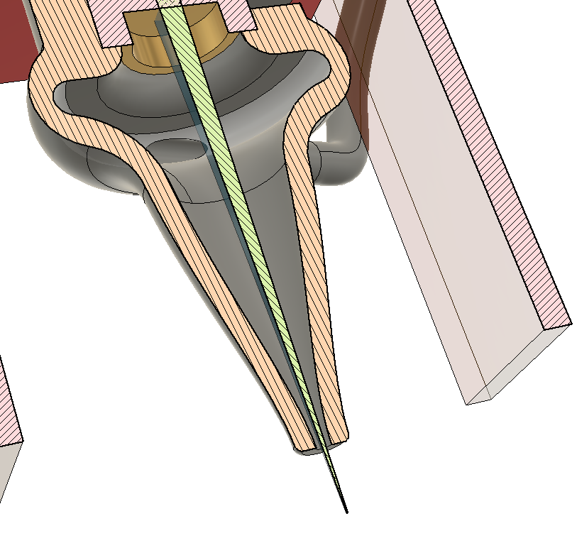
I’m sure I’ll be messing about for a while yet until I decide on the best exit diameter, material etc. The latest iteration finished printing last night so I must get out to the garage and post-process it so I can try it out!
Edit:
I’ve just had a thought that instead of electroless plating or chemical deposition I could try gilding the inside with gold leaf (or more economically copper, brass or aluminium leaf). I’d just need to print the nozzle in two halves so I could get to the inside and then bond it together after gilding.
I’m thinking there’s a correlation between the diameter of the opening and the PSI of the pump. The higher the PSI, the small the opening can be and still get the proper amount of air to pass though. I now have the Vivosun 50W / 1110 gph / .03mpa (4.34 psi) pump. My nozzle opening is currently at 2mm. I’m going to experiment with different diameter opens when time permits.
I started at Ø2.0mm and my current iteration is Ø1.2mm. I’ve yet to try it out to see whether I’m able to mount it so that it doesn’t clip the beam.
Yes, you’ll find a calculator here with formulae. You’re right, up to a point. If you keep increasing the pressure there comes a point where the nozzle becomes ‘choked’ and no matter how much you increase the pressure you won’t get any more air flowing through it.
Michael have you got a printable file for your version and a link to the metal nozzle you are using? Thank you!
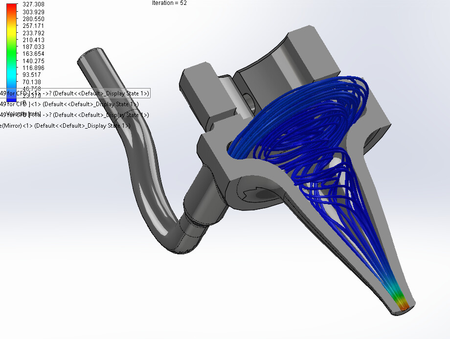
Swirl air flow dynamics is a common tool for internal combustion engines.
The swirl is created in the intake port so when the flow is released into the combustion chamber during the valve opening the air mixture expands due to centrifugal force and fills the combustion chamber better.
For laser etching this could be a disable flow pattern to blow the particles away.
My intuition questions this flow pattern for clean, straight, perpendicular cuts.
Curiosity is pushing me to creating two different nozzle types for my Frankenforge build.
A quick test to see if the beam is centered to the nozzle exit hole.
Place a small piece of clear tape over the nozzle exit.
With air assist off do a quick test fire.
The burn mark on the tape will reveal how centered the beam is to the nozzle center.
If the beam slightly nicks the nozzle edge increasing the hole can be a solution.
Or with a 3D CAD design the model could be altered to center and reprinted.
Otherwise it’s a beam alignment procedure.
Beam Checker 2.lbrn2 (12.2 KB)
This is one of Russ’ contributions. If it fits the nozzle, it should make this easier…
Modifiable to any size nozzle…?

As there any discussions or documentation for the beam checker ?
Watching a few more of Russ’s video’s today … (RDWorks learning)
Rather humbling reminder of how much more there is to learn.