But it does cut lovely in the front right, and the cut gets worse as you move towards the back left. when I up the power to 30% it gives a more solid dot straight away.
This is from Gaussian beam optics. It’s a pdf download link.
I was suspicious, which is why I asked for the photo…
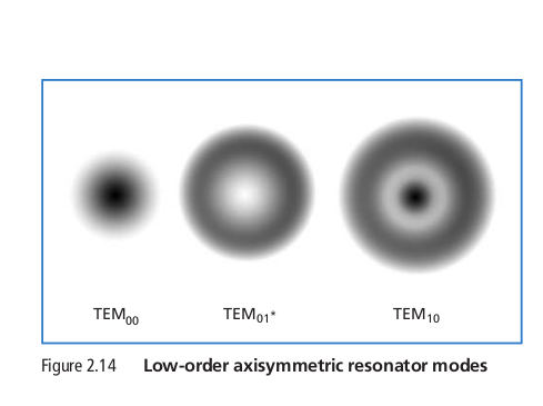
This is how the ‘resonance’ in the tube is actually working. There are a number of modes they can ‘lase’ in, only TEM00 is useful. As far as I know…
TEM is an acronym for ‘Transverse ElectroMagnetic wave’
IMHO, if this is relatively new machine or tube, I’d go ‘from whence it came’ and see if they will help you. I think others will agree, but haven’t stated it yet, is the tube probably misbehaving. Read ‘misbehaving’ as ‘shot’… ![]()
To @dean448 credit, he didn’t come out and say it, but he did say it in a round about way.
Start your troubleshooting where you know it’s ‘good’ then follow it to where is “isn’t”
Just out of curiosity, what temperature do you run your machine (tube)?
Good luck
![]()
I don’t understand why this would only cause an issue as you get closer to the tube (back left) when Front right is a tight even cut, does the beam change over the distance?
The water in the chiller unit is usually between 9 and 12 degrees C.
I have done some messing about, turned the lens over the wrong way (so convex side is down, convex side up) it seems to cut better all round for some reason.
I moved the bed down another 7mm( to 14mm) (focal distance on ramp test was 7mm) and the cut is definately less burnt on the surface in the BL corner, but is still about 2x as thick as the cut in the FR.
If it was a tube error, power supply error, wouldn’t it effect the whole area?
It is clear that the tube is not in a proper lase mode when it’s operating.
You laser is not exactly dead on, I can tell from the targets, the spot is not exact.
The beam cannot really be focused, so what focus you do have varies as the head moves.
Even with a perfectly setup machine, you can’t use a TEM01 beam, as @dean448 pointed out.
That should be fine, my chiller is set at 20 C. I notice a change in characteristics when the temperature changes…
Just for fun, you might see if you can change the ‘focus’ where it’s wide, if that makes sense…
Now is the time to fiddle with it…
I never like to say never, but it’ unlikely a lps problem. Based on it is lasing, with the lps problems I’ve seen, the tube wouldn’t lase at all.
The issue is it’s a ‘beam problem’. I think at this point you are beating a dead horse…
The failure is there is no TEM00 beam produced by the tube, sad, but true.
Good luck
![]()
1 Like
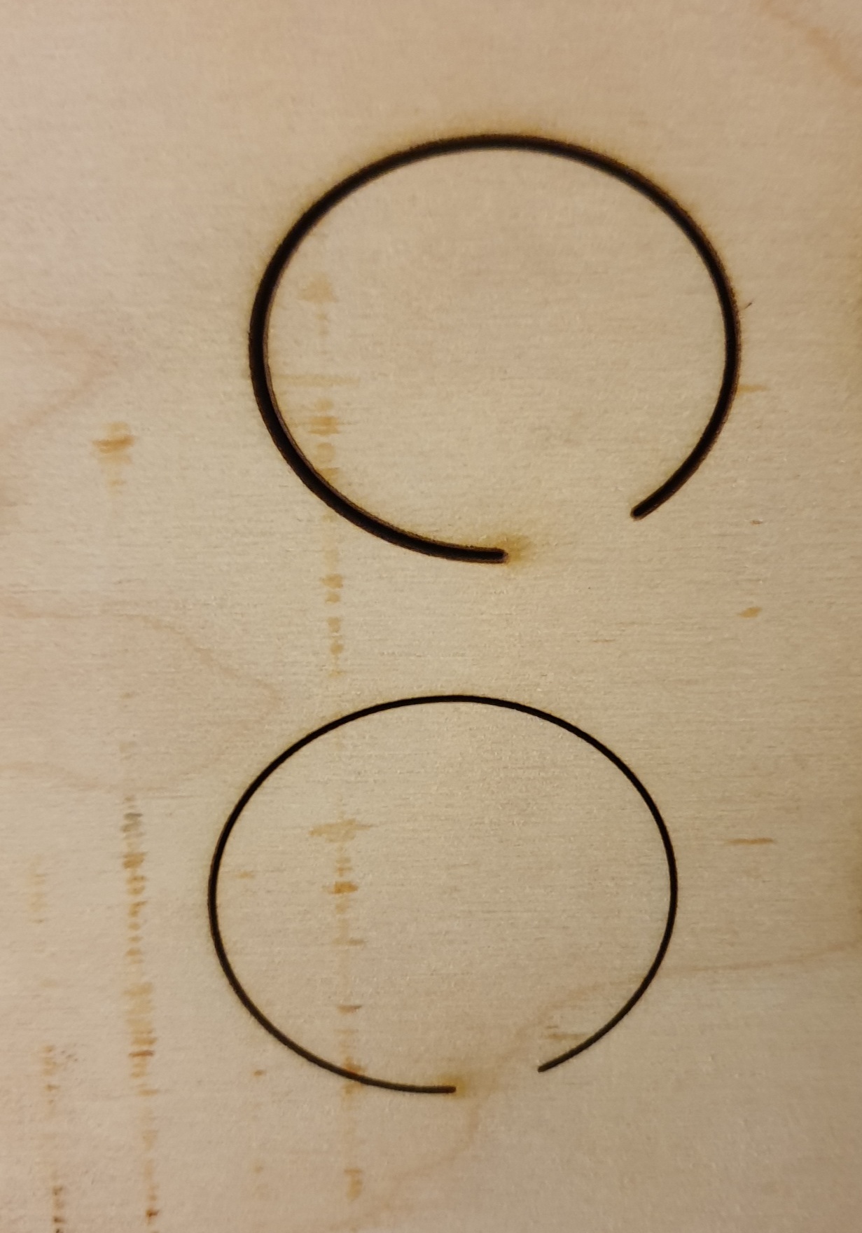
Can you make a new shot on mirror no.1 with a pulse of 250 ms and 20% power ?, and see if you get a point instead of a ring? I can “provoke” my tube to produce the same ring if I want, without the tube failing anything. We’ve had the discussion on this topic before and I think it’s dangerous to judge people’s tube out per remote diagnosis. If you shoot half a second with 50 Watts on a wooden target, no one will be able to see a ring. When your tube can deliver this thin, fine line and you can also penetrate the material in a specific area of your bed, then your alignment is not ok. I think your tube does not hit mirror 1 as it should.
A ray of light cannot change its shape without outside influence.
This is M1m 250ms at 20%
If the alignment was out, would it not get worse the further away from the origin point? ie the Front Right is the best which is the furthest away?
this is M1 100ms at 20%
It’s not dead center, but don’t think that matters?
Ok so I moved the m1 to the center, and am re aligning…again…
Probably so, but it’s running in a known ‘destructive mode’ where it breaks down even faster. You are keeping in an excited, but not lasing state. One of the reasons you have a minimum power setting on your controller…
Usually you’ll get variation and strange patterns at low current, as it’s not lasing.
The shot of the ‘doughnut’ was done at 20%. Power areas are pretty clear.
If it’s not lasing properly at 20%… good luck..
@LaserCuttingPro you only need to do @bernd.dk test at mirror one. Don’t need to realign.
I don’t ever like to say it’s hardware…
![]()
Ive looked at the cuts through magnifying glass…
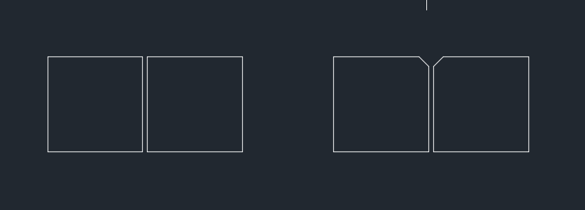
Left is how it looks at the FR, Right image is how it looks BL.
Both cut through the material, but the more towards the BL you go the more bevel you get and hence the cut looks wider and burnt.
Jack, I’m just saying that with a “wrong” time and power setting you can provoke or rather, get an image that is very similar to what you correctly describe. We completely agree that there should always be a nice round dot coming out of the tube and hitting mirror 1, as best as possible.
Regarding the mirror1 and the align of the tube, with a distance of approx. 50mm, you can hardly see at what angle the laser beam hits, even if it makes a clear mark on the tape. But the error increases with length.
What is not understandable to me is that you hit the spot in all 4 corners with mirror2 and mirror 3, separately - then everything should be perfect.
Of course you have checked the mirrors and your lens for errors and correct placement …
… good that it’s not me, I will be impossible to deal with until the error was found ![]()
Did you try an do a short ramp test in these areas?
Assume you have a small workspace in the fr and bl, do ramps and see if the focus is different.
It would be an interesting test to see if the ramp gave you a different focus point in the two different areas.
If the beam doesn’t hit the center of the lens, the output side will be at an angle… This may be the bevel you speak ot…
Do you have 20mm mirrors?
![]()
Great suggestion, especially if there is a honeycomb bed
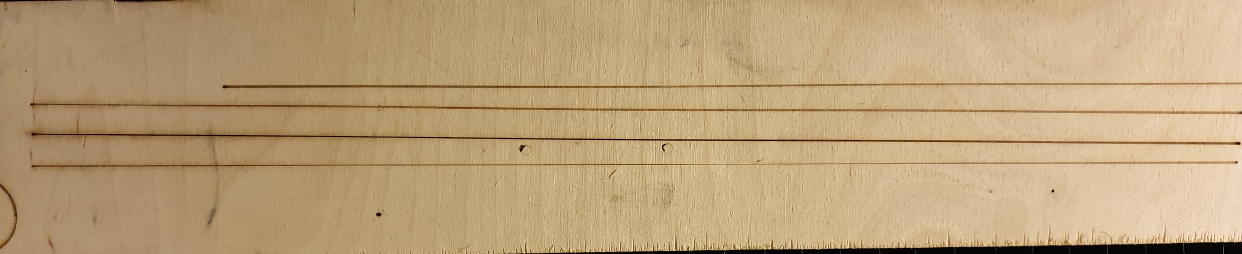
This was the ramp teststhe bottom line was from the FR, the other 3 above are from the BL at different powers.
Ramp went from 2mm to 20mm over 450mm long.
The focal point is about the same 7/8mm…but the line over all is just thicker.
It’s the same with a pulse dot. set at 100ms, 20% power. the dot at BL is 2 or 3 times the size of the dot at the front.
I think we can discount alignment (as it would get worse the further away) and focal distance and bed level (it’s a slatted aluminium bed, not honeycombe) is very flat and level.
I put in a new controller about 3 months ago (RDC 6445S) but don’t see how this could effect it, as far as I know there are no settings to change the way the laser fires over the distance of the area.
New mirrors (25mm), new lens (20mm)
New power supply with ma display added to front of the machine, mamps are stable.
The Tube was new last August (£750 EFR 100w tube) I will be very pissed if this is causing the problem, but it is slowely becoming the only possible thing that could cause a problem like this. Somehow the beam must be different depending on the distance from the source, is that possible? Is there any way to check this?? power meter, or frequency meter maybe?
Testing with a power meter will be able to give the indication of “where” you are losing power or focus, but it is quite expensive to buy such a device.
For info only, I do my ramp tests at a significantly steeper angle, it is in this way easier to see the focus area.
As long as your chiller has the capacity to hold temperature during high wattage cuts, I’d increase it to 18 to 20 deg C. You may also want to double check what the manufacture recommends for coolant. There have also been comments about that on this site.
I had this same issue. did every thing that you have tried. The one thing that made the biggest improvement was fixing an issues I had. One of the screws that hold the laser head at a right angle to work had striped. I had to replace it and then realign the head. to realign the head run the head down to the focus point and pulse the laser that will give you a reference point then raise the head up two or three inches and fire the laser again you may need to hold the pulse longer to show a burn circle, the first point should be right in the middle of the second, if it’s not then you need to adjust the head and try it again until they are. if you find that this alignment needed to be done, you will probably need to realign everything again. I know that after I did this my engraving improved greatly and my cut power requirement for 1/4 inch material went from speed (12) power (80) to speed (15) power (50) I have an 80W laser. hope this helps
Dan
2 Likes
I do this as part of the alignment anyway, the verticle alignment of the head is very good all over the machine.
When I do spot checks (pulse) nearest the tube with pulse a dark spot, furthest away just marks the tape with a light mark, and takes 2 pulses to mark it the same (80ms 20% power)
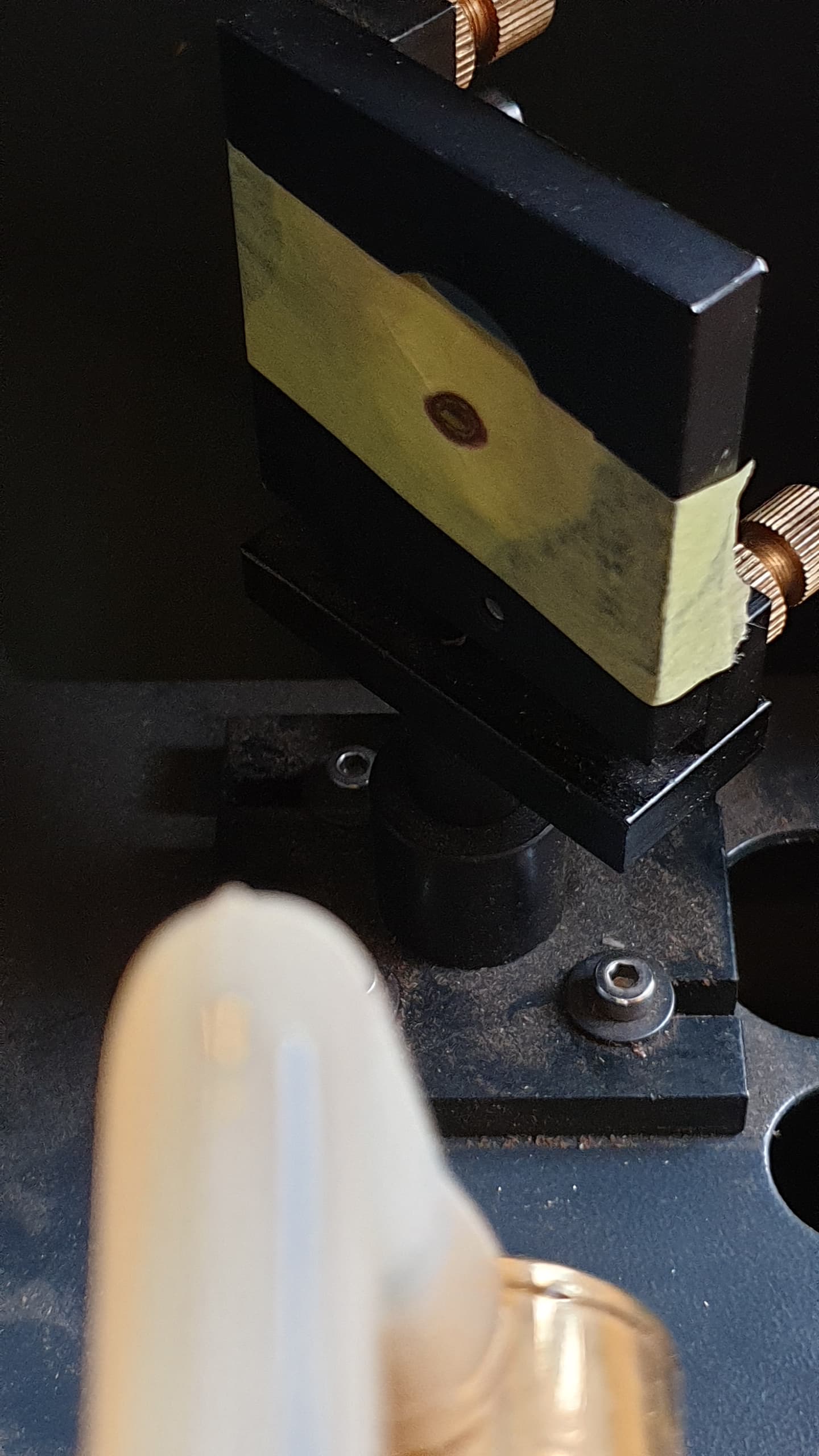
Today I went to look at the tube to see on it’s sticky label what model and the date on it. The label was under the tube, so I rotated the tube to see it, and noticed another label. Bright yellow…This side up!
So the engineer that installed the tube last August put it in upside down…
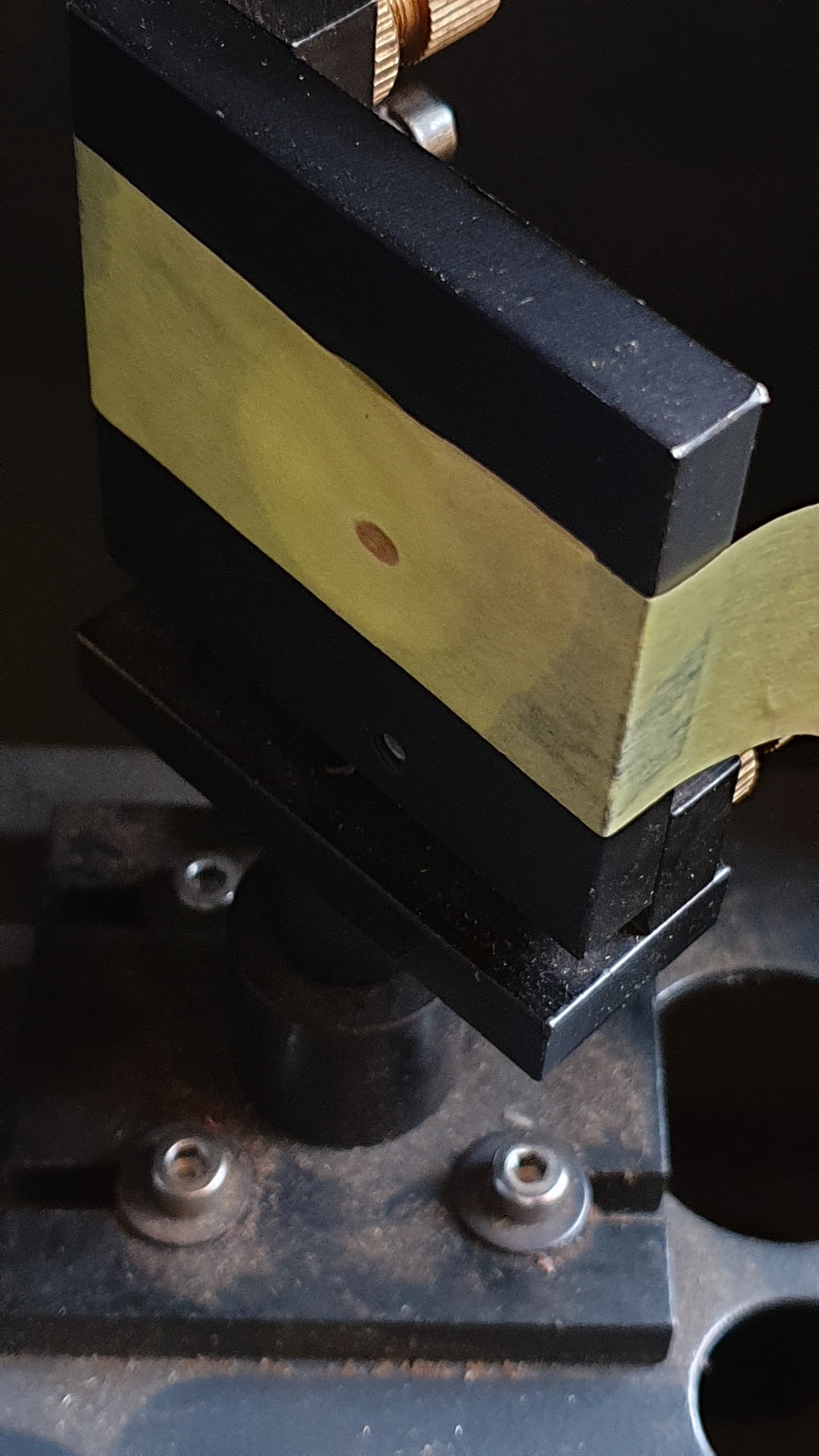
Also the mounting points are not where marked on the tube (1 is, the other is about 2 inches away) guessing this is less important
It is a EFR F4 tube.
I’m assuming it needs to be the correct way up, why else put a bright yellow sticker with this side up on it??!!
Could this have ruined the tube? (obvious answer I expect)

This is short video of the end of the tube when firing, should it be hitting the brass surround like this? is this normal?