Im still dealing with this. I have replaced all bearing and roller wheels on my gantry carts and my laser head is running on a linear rail now.
I have run the laser while side loading the head to make sure its not jiggling and still get the same result. I have even drawn my files in other programs to see if it had something to do with it.
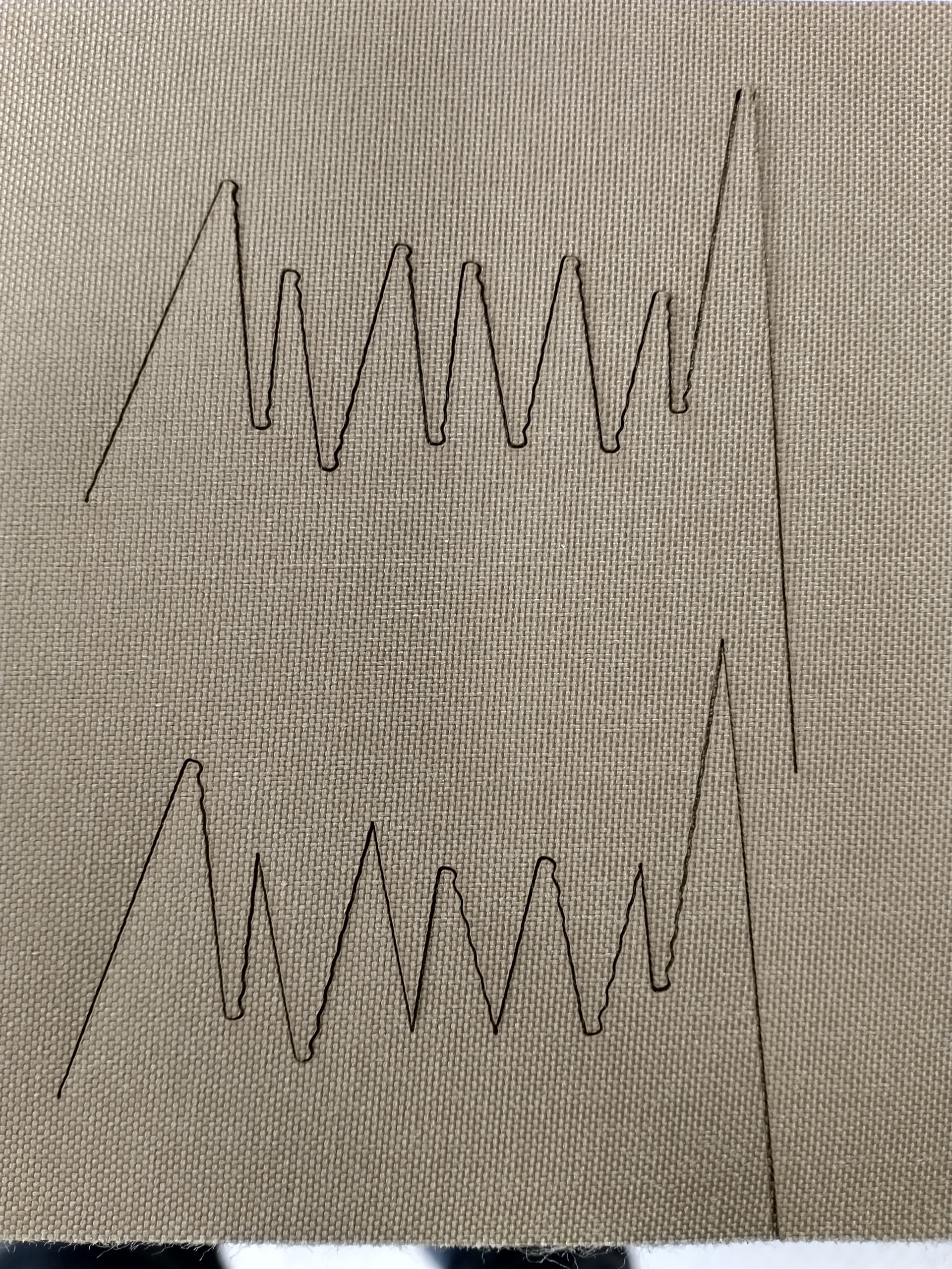
Cuts I can make at 60-120mm/s I am forced to slow down to 30mm/s if they involve radiuses. as soon as I push over 30mm/s I run into jagged cuts. Draw a square , cut at full speed. If it has a .125" radius on the corner you get the jagged cuts.
Today thinking about this I was curious is this could actually be stepper driver settings. Something I do not have a lot of knowledge about.
Well tensioned and tensioned to various levels throughout trouble shooting. I have run them tight to loose with the same results.
Just to add, the chatter is always to the inside of the radius. With a loose gantry roller or belt I have seen the bounce of the direction change show but not a ripple out from the direction change. normally worse with a sharp change like a corner not a smoother transition like a radius?
Looks like your cutting fabric? Are you using air to the cut? Is it possible that the air is causing the fabric to ripple? What does it do if you cut thin wood?
Trying to figure out why if something is loose that it only affects radius cuts and never a corner regardless off degree or speed?
Maybe I am missing something?
Replaced and adjusted all bearings and roller including tensioners
Replaced and adjusted belts
Checked drive gears set screws on steppers
New linear rail system on gantry
Verify square and true X/Y rails
What I see zooming into your photo is the head coming out of a radius and wobbling either side of the new vector until it’s on the path it needs to be on. To me that looks like a problem with PID controller tuning.
PID is Proportional-Integral-Derivative; it’s a method of predicting the motion of an inertial system in software. Those three terms model, respectively, the present, past and future motion of the system. It’s not a physical controller, it’s a model of a physical system in software.
It looks like the derivative term Is overshooting. You might be able to change that behaviour by changing the allowed acceleration of the head. If it’s genuinely a hardware wobble then reducing the permitted acceleration might fix it. If it’s the stepper translation module outputting the predicted overshoot of a modelling module that could also drive servo motors, increasing the permitted acceleration might help. If you can change the actual PID parameters, setting the D term to zero would stop the prediction of future motion.
I’m also wondering if it could be related to microstepping in the stepper controllers, but PID fits the picture better.
Don’t change any settings that you can’t change back. Backup your setup before you start and take notes as you modify values.
Thank you! Im more a hardware type. I just have a feeling that this issue is the result of the laser just doing what it is being told to do(software). Various mechanical adjustment did not make much of a difference till things were made so loose that it was an obvious wobble. I’m sure it something that my lack of knowledge and poorly translated manuals keeping out of my grasp. This DIY rig has been running well with just this gremlin haunting me.
One thing I failed to mention, The ripple is always on the backside of the radius
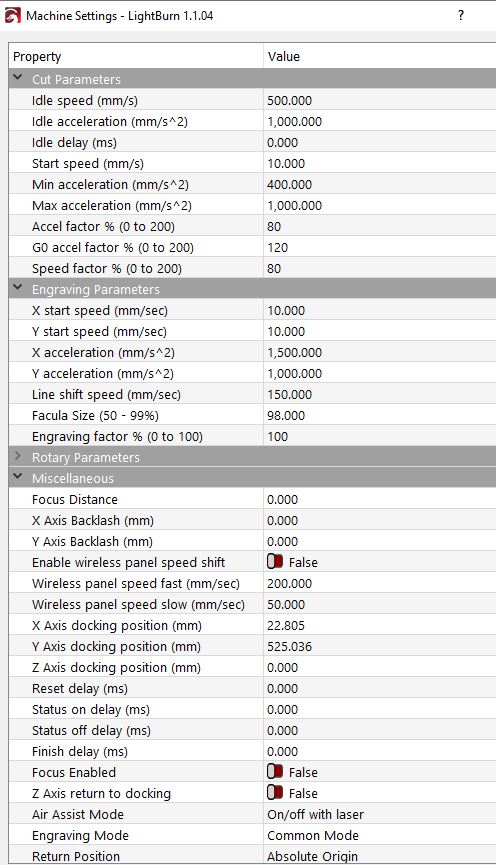
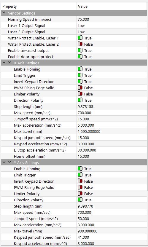
I have some reading up to do on my Ruida 6445G, P.I.D. etc. Basic machine setting where taken from some online resources as starting off points. I posted them as their may be a glaring issue to those with a better understanding.
I agree, almost certainly a software issue. Your line-to-line direction changes are crisp and clean. Put a radius in there and you get wobble coming out of the radius.
Just a thought, and not suggested as a solution, what happens if you replace your radius arc with a polar array of line segments?
Your cut parameters look a whole lot like mine, but since you built your own machine all bets are off after that. I’m assuming from your engraving acceleration parameters that x is head translation and y is gantry. I’m also guessing that your picture has x horizontal, which makes it look like the problem is on the x axis. What happens if you rotate the cut 90 degrees? Does the problem look the same?
If it were me I’d try modifying your cut setup parameters one at a time in isolation and see if anything changes the result. I don’t know what the ‘factor %’ parameters modify, but I still think the problem looks related to speed and acceleration.
That wouldn’t have been my first assumption from the artifact but easy enough to check.
@LunarConcepts, are you able to test using RDWorks? That will tell you if it’s exclusively a software thing or something in hardware or controller config.