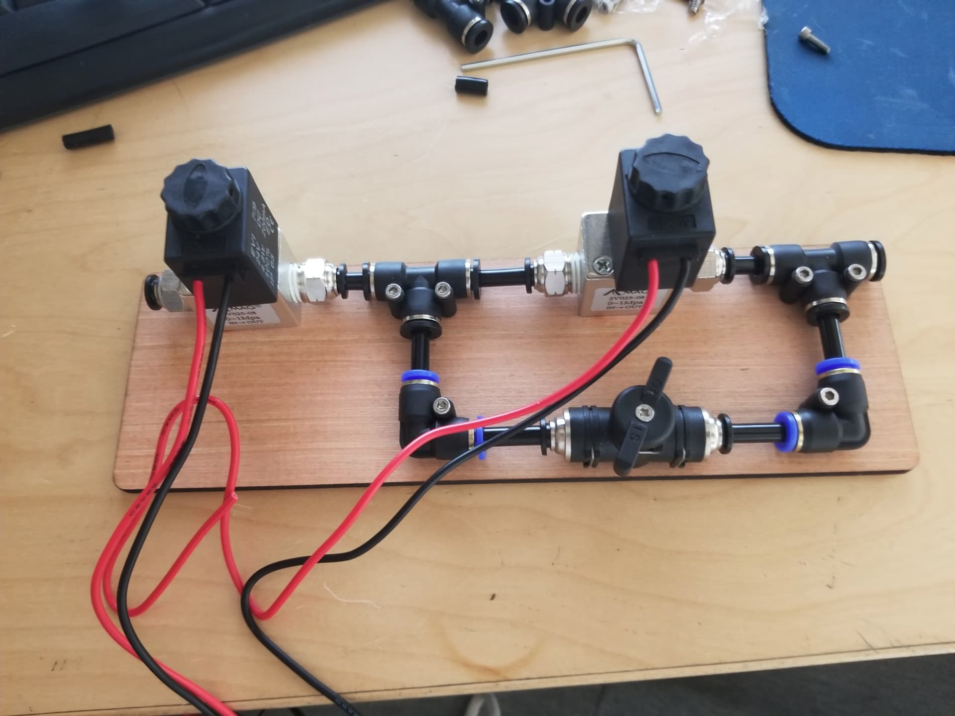
I have a new OMtech MF2028-80 laser that I have upgraded the air assist. My laser came with the KT332N controller. I am not getting any air when cutting or using the manual “aux air” button the cabinet. I think I have isolated the issue to the controller not “driving” the Aux Air pin on the controller to ground when enabled. I am using the Tailonz 2V025-08 solenoid which seems very common in the forums for these lasers
Here is what I have tested.
(1)getting air into the solenoid about 15 PSI
(2) non powered resistance across the solenoid coils measures 100 ohms
(3) I have verified with a voltmeter that I am getting 24 volts between the “24v terminal” and ground. I have 21 volts between “Aux Air terminal” and ground. And finally, as one would expect from the math, I see about 3 volts between the 24v terminal and the Aux Air terminal. These values are when aux air is on. (when it is off, Aux Air terminal is 24v)
(4) I have tested this both while the laser is cutting as well as when toggling the “aux air” button on the laser control panel.
(5) I have aux air enabled in the KT332N parameter settings
(6) Aux air is turned on for the layer in Lightburn when I run my tests.
(7) Finally, when I temporarily connect the solenoid between 24v and ground it does blow air.
I have read in other threads about the solenoid being able to sync the current to pull the Aux Air terminal to ground. Since this solenoid seems very popular I would that that is not the issue.
It may be the solenoid requires more current than the controller can handle, per Section 7.2 of the KT332N manual:
Its maximum driving capacity is 300mA, which can directly drive 6V / 24V relays, light-emitting indicators, buzzer alarm devices, etc. If user wants to drive valve, a relay is strongly recommended to be added between the controller and the valve.
The description of that solenoid is rather thin on electrical specs, it seems to draw 4.8 W at 24 VDC, which works out to 200 mA and should work just fine. I look at those two number and think it’s right on the hairy edge of not working, because I do not trust either value very much at all.
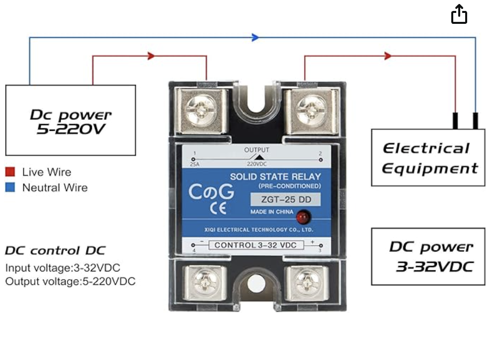
Reasonable people disagree on this, but I use a DC-to-DC solid state relay to reduce the load on the controller:
My thinking is that controllers are expensive and difficult to repair, while solid state relays are cheap and readily available.
The relay has a cheerful LED to indicate when it’s active. If it doesn’t light up when you think it should, then look for:
A wiring error
A configuration error
The solenoid valve has killed the controller’s output transistor and you’re in a world of hurt
I think you pretty much solved that your output isn’t going low (enough) to activate the solenoid. It also sounds like it’s trying to go low. That would indicate it’s the sink transistor within the Ruida being the most likely source.
Did you put a snub or flyback diode in the circuit?
I’d open a conversation with the vendor about this… never know how they’re going to take it
I had two documents on the 6442 that showed a maximum current rating in one as 300mA and 500mA in the other. So I have to agree here…
However, these are supposed to be designed for and are used all over the world commercially driving solenoids without any intervening hardware. I’ve hooked this kind of stuff up for over 1/2 a century as the manufacturer suggests and have had little trouble… that excludes mechanical relays…
A 6¢ 1N914 works fine
The beauty of these are we can use, whatever floats our boat or blows our skirt up… however you phrase it, we get to choose.
I still stick with the diagnosis that the pin is attempting to operate or there wouldn’t be a drop down to 21V + The solenoid works fine when manually connected to ground and 24V… that pretty much makes it a controller issue.
I’d call the vendor, at least start a conversation…
Basically, they come in two flavors depending on the output, to control either AC or DC circuits. The input side uses an optoisolator and expects to be connected between the power supply and an active-low controller output pin.
An AC SSR to turn the air pump on when the controller activates the STATUS output during the job
A DC SSR to turn on the high-flow solenoid when the controller activates the WIND output as set in LightBurn
FOTEK SSRs were so widely counterfeited it was basically impossible to buy a known-good unit; they have since disappeared from all the usual consumer-grade sources.
Thank you for the links. I ordered one of the DC units. Last question. Would you use the 24v supply (output) on the KT332N for the supply for the output or would you use a seperate (external) source?
Positive side of the ssr goes to 24V the negative side goes to the controller. The controller completes the ground for the ssr. The current draw on mine is <20mA, so it’s not really and current for your controller… If I’m following your question…
Thanks! Just to clarify, the Input (bottom in the attached photo) of the SSR is connected between “Aux Air” and 24v on the controller. My “load” is the solenoid. Since there is not polarity to Solenoids, I believe I attach one wire of the solenoid to one terminal of the SSR, the other wire of the solenoid to GND on the controller, and then a wire from the 24v on the controller the the remaining terminal on the SSR. Essentially the SSR is “switching” the 24V to the Solenoid. My concern is if the 24v terminal on the controller can handle the load or if you recommend an “external” 24 volt source (in which case I would move the “grounded” wire on the solenoid to the Ground on the external source so the voltage reference is accurate. Thoughts?
Reasonable people will disagree, but I wire (relatively) high-current loads directly to the power supply, rather than the ever-so-convenient controller terminals.
It is probably true that the controller’s +24Vand GNDoutput pins have wide PCB traces from the corresponding power input pins, but I still prefer to keep all that current out of the controller.