I have a 100W laser with a Reci W2 CO2 laser tube. The Power supply is a HY-T100. I am having issues with power settings. For starters at 85-100% power it is only pulling 21ma on the gauge. Doesn’t change from 85-100. I tried adjusting the “pot” on the side of the power supply but I saw no change with adjustments. The other issue I have is if I am just doing an outline and I set the power down to 10% it will almost cut through the material on initial start, on some material it will pierce all the way through even at 10% power. Do you think this is a power supply issue?
What controller do you have?
Some things to check,
Is laser power capped in the controller settings?
Is the laser power capped in LightBurn?
I have a Reci W2, I would not consider it a 100W laser. To get maximum life out of it, limit to 25/26mA once you get the power limit sorted out.
Because you have made adjustments to the LPSU, you will want to check some things when you get it working,
I set mine to give 26mA when power is set to 99%. Then, you will want to check the power at 50% and see that it is near 13mA. Adjusting that screw too much can make the LPSU non linear.
Joel,
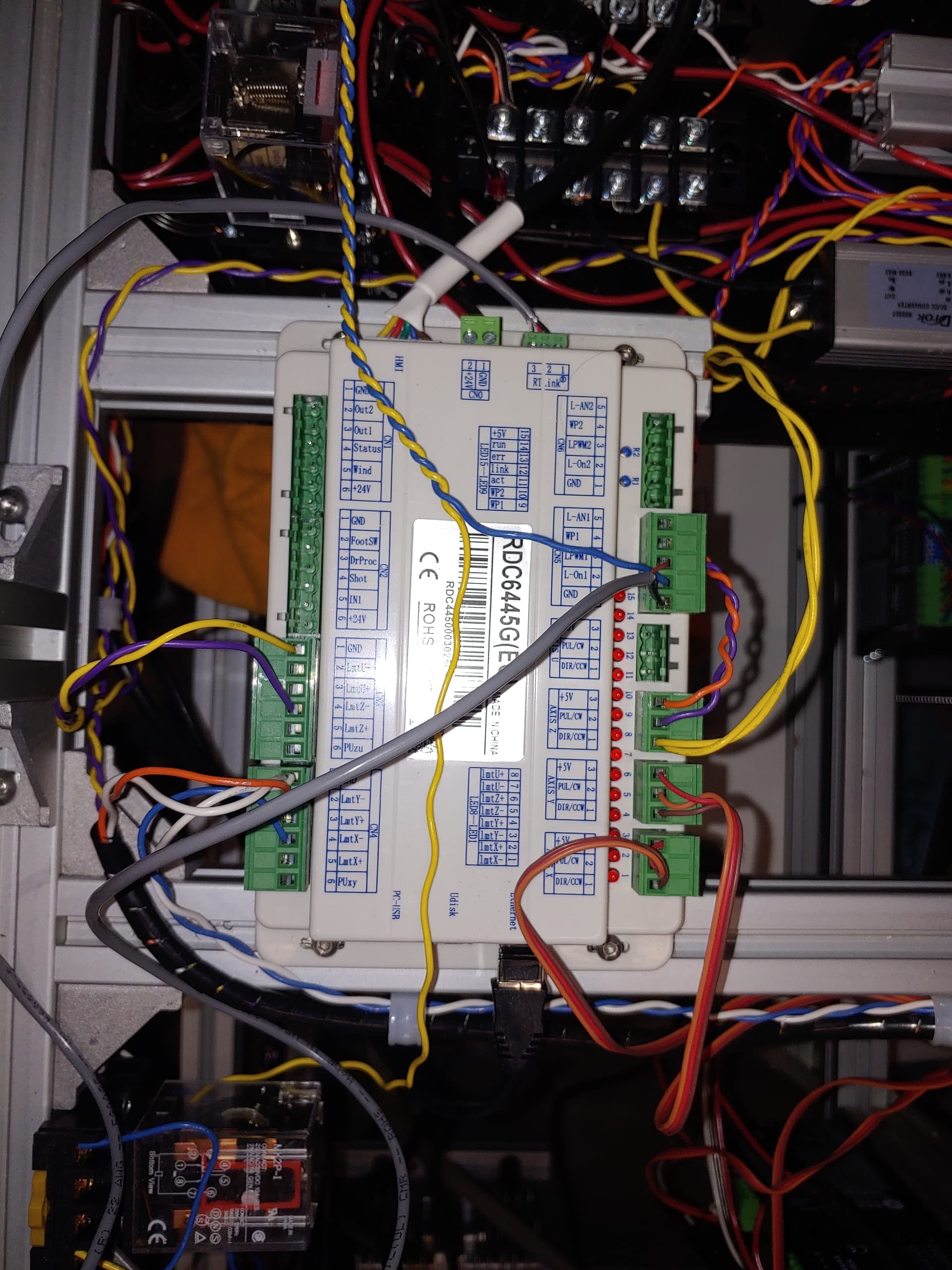
I have the Ruida 6445 controller
I’m not sure if the power is capped in the controller or in lightburn, how do I check these?
I looked and can’t find what I think is the Lightburn setting, I thought/think it has one.
For the controller, make sure the controller is on and connected to LightBurn,
Go to edit → machine settings → vendor settings
You will get a warning, hit yes to continue.
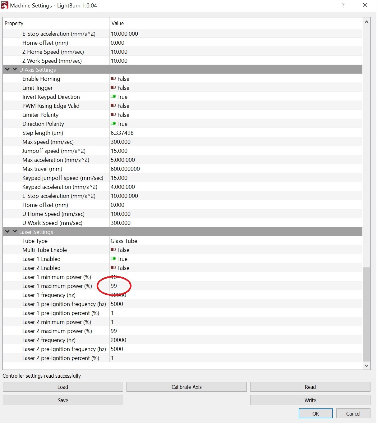
Scroll down to laser settings and check whats set.
I set mine for 10 min and 99 max.
Joel
Here is the screenshot of my settings

It shows minimum at 1 and max at 99. Not sure why minimum is 1 anything below 5 and it won’t fire
1 is just the default in the controller. I set mine to 10. For me from cold my tube wont fire until 15 or so. Once burning, like for 3D engraving, it continues to fire until about 10.
Anyway, back to your problem, leaving the LPSU off, can you measure the control voltage going to the LPSU?
Another thought, when you fired at 99% and only saw 21mA, was that through LightBurn or through the control panel? If through LightBurn, you could try setting the control panel to 99% and press the fire button. See if you get the same result.
Is your system actually a dual laser system? If not, turn #2 off, not sure if perhaps the controller does something odd with power for dual lasers.
Yes when I test fired the laser it was from the controller. I then did a test cut with lightburn and the results were the same. At 80% it read 20ma and 85 to 100 read 21ma. I will try to get a voltage reading. Also yes I only have a single laser. I will try turning the dual laser off and see if it changes anything
The peak current of Reci W2 is 25-28mA. The phenomenon you described has nothing to do with power supply. You should check your software Settings, such as switching delay, switching delay and so on
Anoxin
Is this a setting in lightburn or in the controller?
Looking at your controller laser settings, they look OK, except turn off multi laser and disable laser 2 ( not sure that will actually make a difference ). Your controller is set to 99%, so fine.
The fact you did do the test from the controller, means it something other than software ( LightBurn ).
Still would be good to know what the actual output from the controller to the LPSU is.
Other items could be, are use using the PWM output or analog? What does the LPSU require? If you are using the PWM out, is there a specified PWM frequency the LPSU wants? You are currently set to 20KHz.
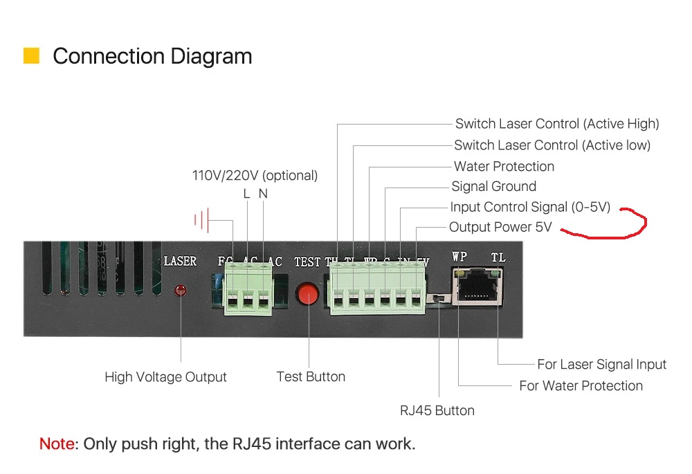
I just looked up your LPSU, it can take 0-5V input or PWM ( same as my HY LPSU ), nothing to set, it just works.
The brute force way to test would be to connect the LPSU input to 5V ( available on the LPSU ) and then test fire and see what you get.
You said you changed the adjustment screw, you might have to revisit that. How many turns did you go?
The controller
Joel1,
I turned off the multi laser and laser 2 but no change. I measure 4.5v at the LPSU and 250V AC at the LPSU. I turned the adjustment screw approx 2 turns in half turn increments each direction and saw no change.
Anoxin,
I did not see the setting you were referring too in the controller
Hi,
4.5V seems like an issue. Are you using analog out or PWM out from the controller?
Try disconnecting the controller from the LPSU laser power pin and connect the 5V out from the LPSU to the LPSU laser power pin, then test fire ( you should still be able to do this from the control panel ). This should be full power so be careful. The adjustment screw on my HY is a 20 turn pot end to end and clockwise increased power.
Joel1,
I do not have anything plugged into the 5v output. Also I was reading 4.5v between the “IN” and the “TL” wires
TL is what the controller pulls down to fire the laser. To check the voltage on The IN pin you should check between IN and “G”. The controller may not be pulling the pin all the way to ground.
So recheck what is on the IN pin referenced to the G pin. If it’s still 4.5V still try to connect the IN pin to the 5V pin.
The 5V pin on the LPSU is a 5V source. You want to remove your blue wire and put a jumper wire between it ( the IN pin ) and the 5V pin. Just remember that when you fire the laser, this will be full power ( +/- what ever screw adjustments you did ). You can still fire the laser from the control panel with cover closed.
What we are trying to get to is if you measure 5V on the IN pin and you still can’t get full power on the laser, There could be a problem with the LPSU, the tube, or the meter itself.
Joel1,
So I check the voltage from the “in” pin to the “G” pin and I do not have any voltage readings. The only voltage readings I get are between the “IN” and the “TL” I did check continuity from the “G” to ground and I do have continuity to ground so not sure why I am not getting any voltage between them. I also tried it with the laser running and only had around 0.6V not even 1V.
I have the same controller. I will take some measurements on mine for reference.
The wire colors are odd on your LPSU ( not that there has to be a standard that is followed ).
It might be good to trace where those yellow and red wires go.
Is this laser a DIY, or made by some company?
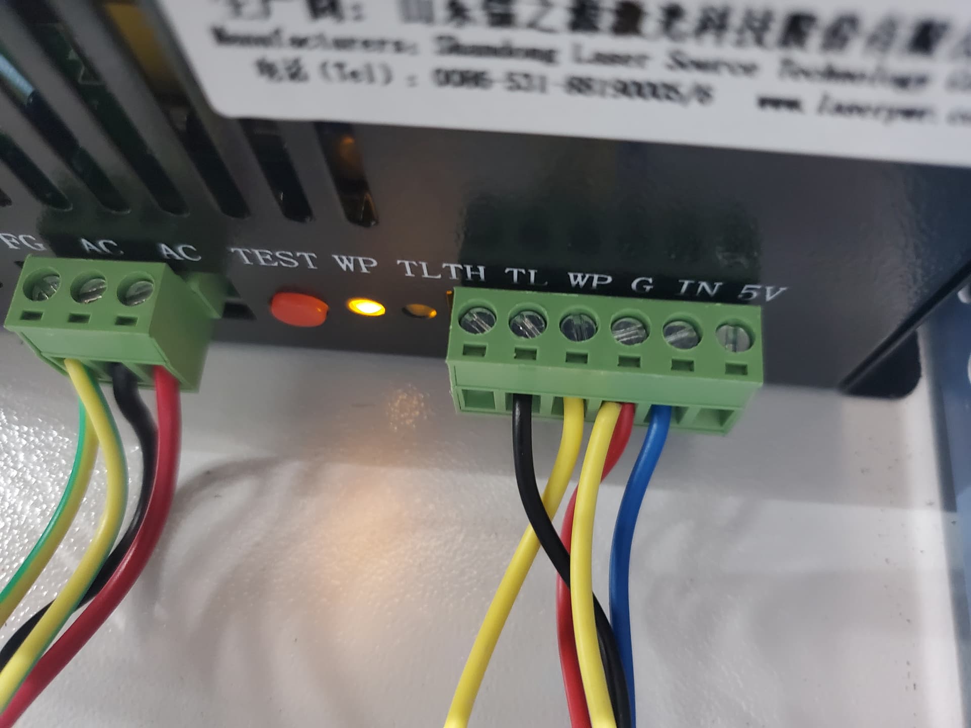
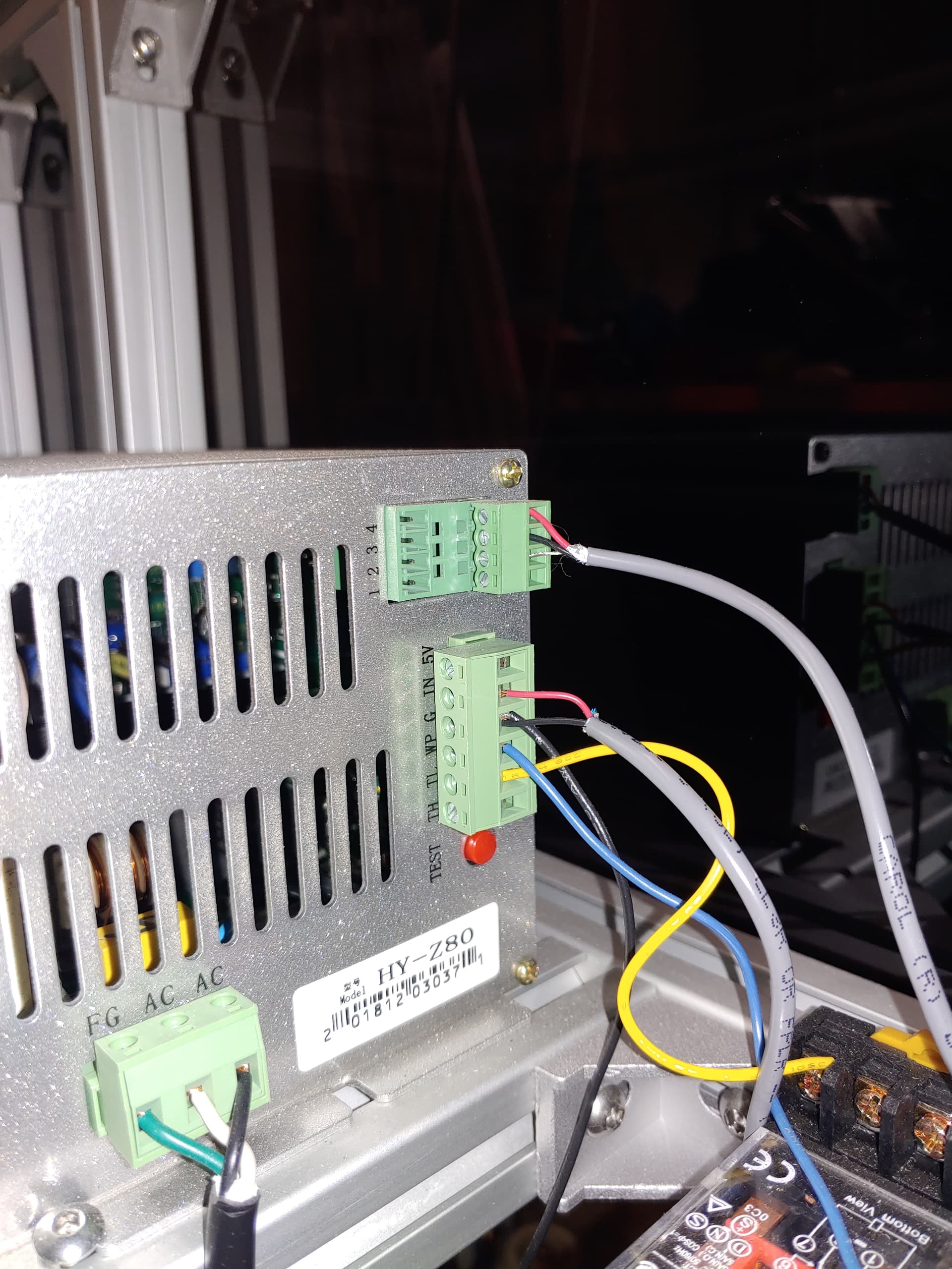
First, here are some pics of how mine is hooked up. I used a shielded cable ( probably not needed ) to go from the controller to the LPSU.
When I set my controller to 99% power, I measure 4.93V at the LPSU IN and GND pins.
I’m able to set the LPSU to give me 26mA through the tube.
If you are not measuring voltage between IN and G, that’s a Problem, check the wiring.
Joel1,
So the yellow wire off of the “G” goes to the laser on/off switch then to the water flow sensor and then to the “WP” on the LPSU. The Red wire from the “G” goes to GND on the “CN5” block of the controller. The blue wire on the “IN” goes to the L-AN1 of the CN5 block of the controller. The black wire on the “TL” goes to the L-On1 on the CN5 of the controller. When I hold the pulse button down at 99% power I do read 4.7V between the “IN” and the “G” and pull 21ma on the meter