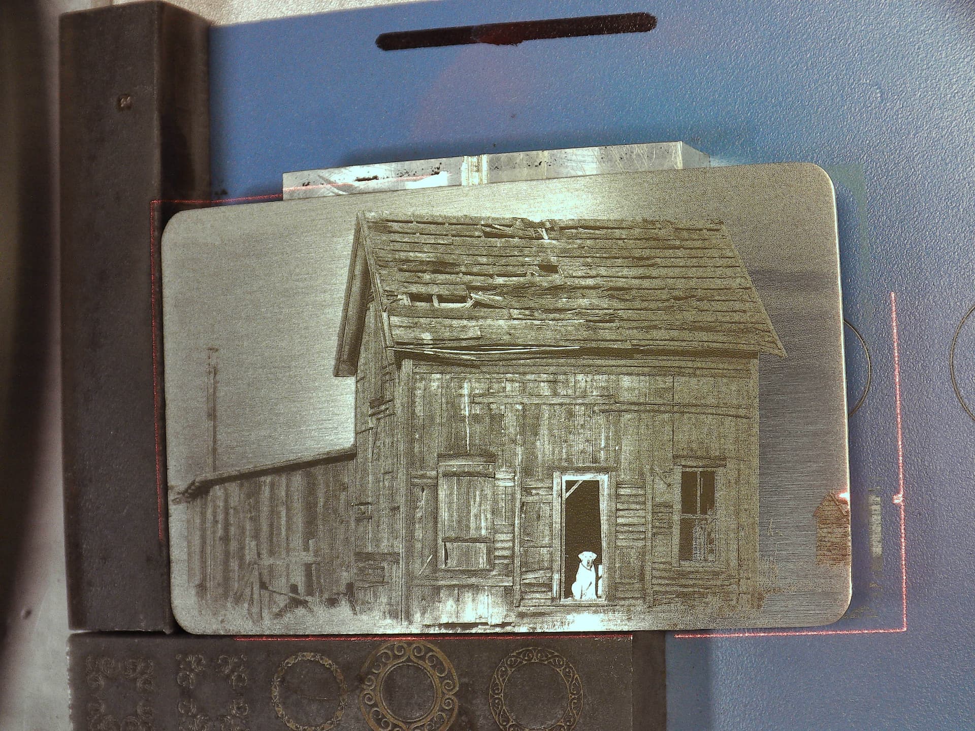
Thanks again. It’s a real Black Dog having this problem, but you have prevented a Communication Breakdown and you may still help me find my Stairway to Heaven.
Let’s have a look.
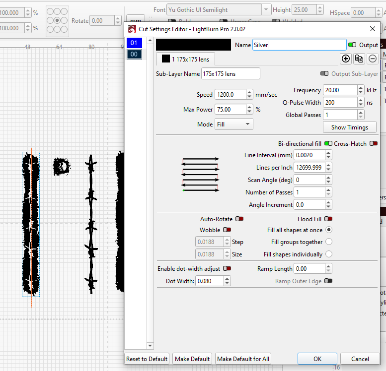
Run whole shapes if possible
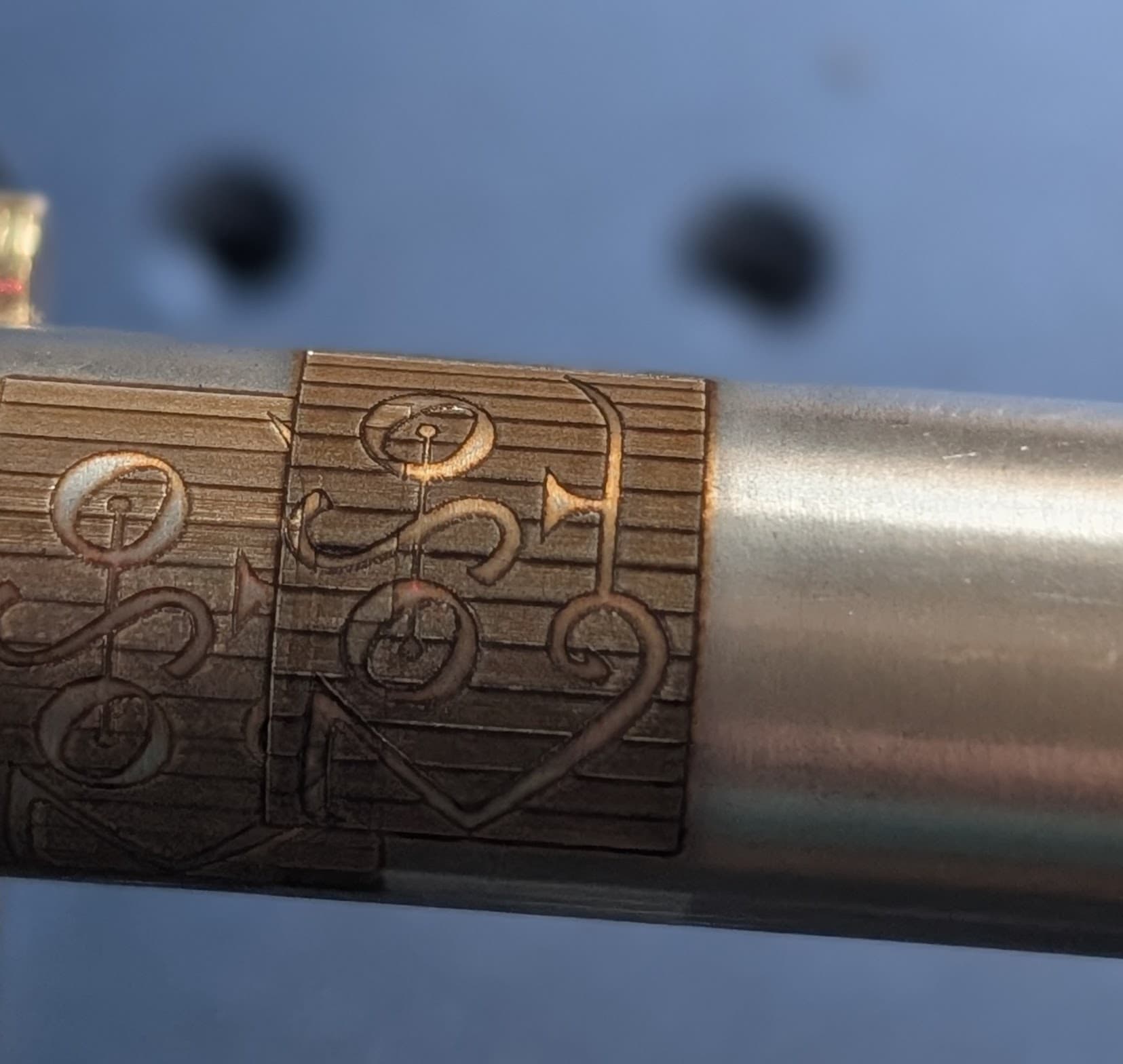
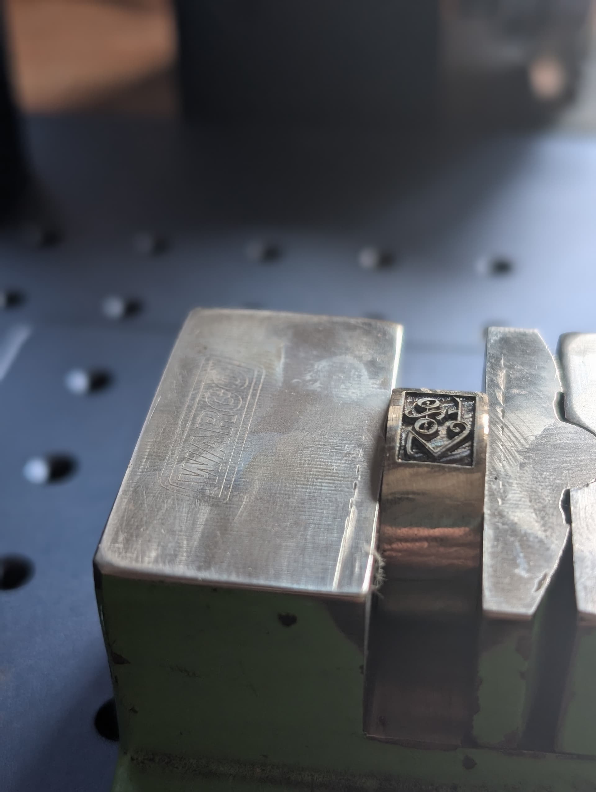
In the case of the image I’ve used in my photo, I don’t know what constitutes a shape. Does the software try to work out what the shapes are, or does the user define them? How is it likely to treat the Zoso image/vector, for example? Are letters shapes, do they need to be closed shapes if it’s a vector, etc. I’ve had a look online but haven’t found a clear explanation of the Run whole shapes if possible feature. I’ll just try it today and see what happens.
Existential question: if Lightburn treats the whole Zoso image as a shape, then do I need the rotary at all?
Depth and power (like Led Zeppelin)
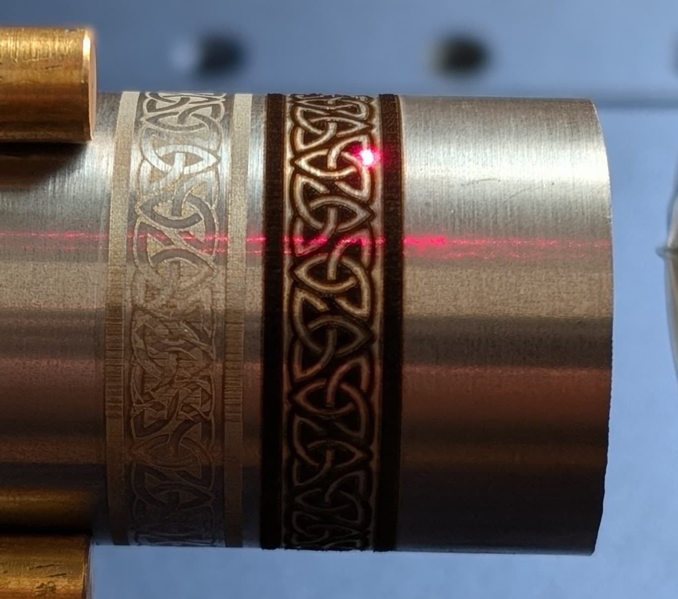
Yes, I probably am using too much power. This is titanium and it lases like it machines. It can’t conduct any heat and will move around and decide to melt, anneal and then harden seemingly as it pleases. If I dial back the power I might get it to behave better. In fact I know it does because I’ve tried it.
I drive a fast car. If I kept my foot down on the loud pedal too long I wouldn’t be here writing this. The same probably applies to engraving. Too much power equals bad. I’ll turn down the power and do more passes. Like driving to the shops in a Nissan Leaf. You get there in one piece.
I think that the grade/alloy of titanium really matters. I’m using 6Al4V (Grade 5), which is way harder than pure Ti and makes for more durable jewellery, but it’s a pig to machine. That personality seems to translate to laser engraving. But I specialise in Titanium so I really need to get this right. Another fun fact is that I use titanium damascus: different alloys pattern welded together. So I can expect varying results across alloy boundaries. With any luck I can make a feature out of that and make like it was intentional all along.
Number of passes
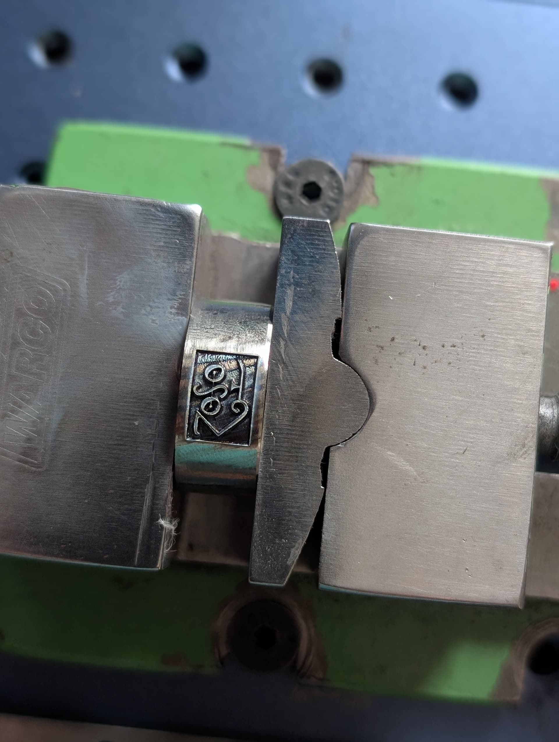
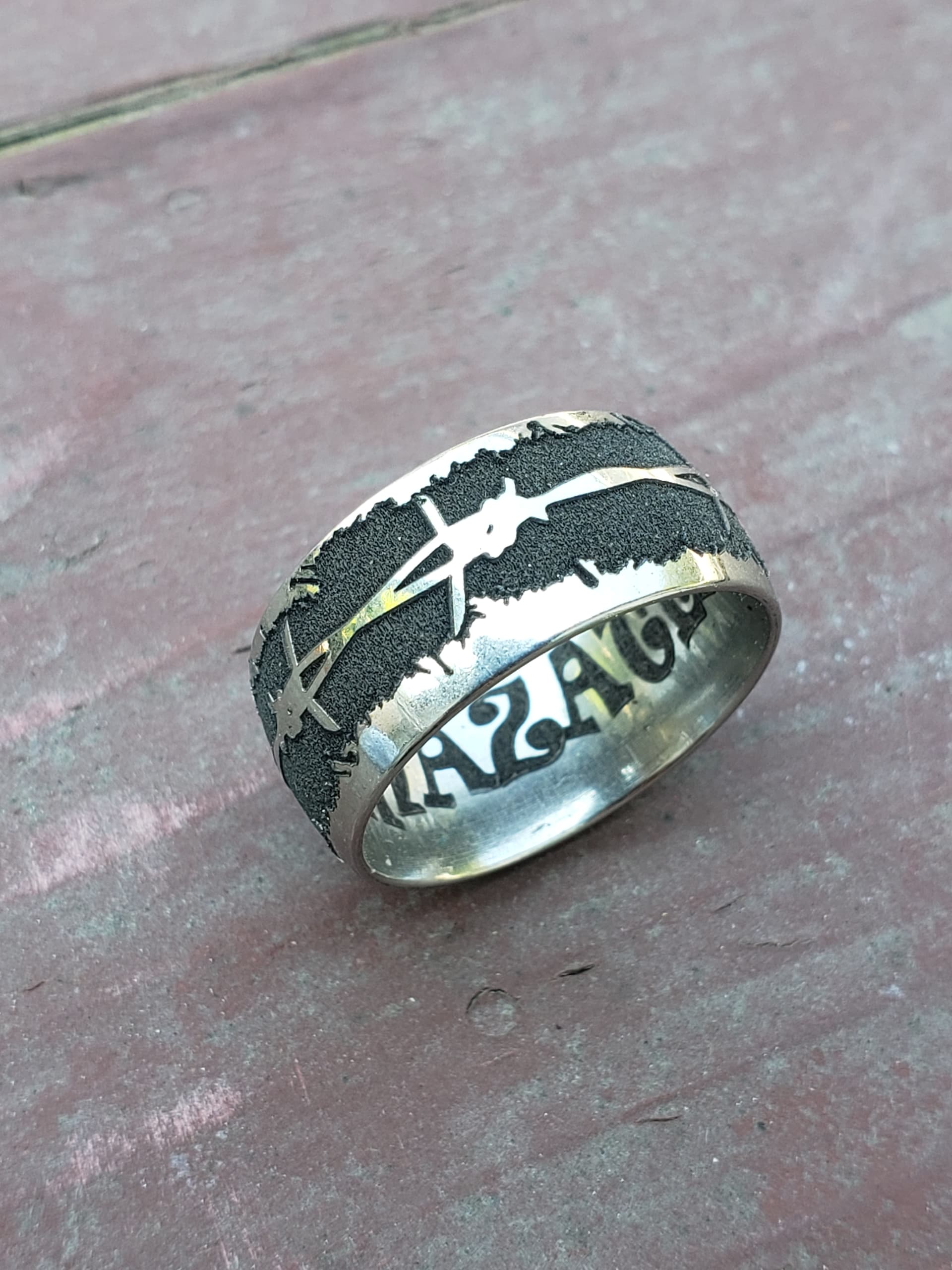
One Titanium-specific deep engraving settings page recommends 450 passes. That’s on stainless steel at 20 watts, 900mm/s, 180 kHz. The deep Zoso ring above was 60 passes (but without the rotary). I tend to do a few passes, observe, and run some more until I’m satisfied.
The deep engraving settings I’m using come from apparently credible sources* and they are specifically for titanium, but they may may need significant modification to work with my setup.
In my Zoso ring photo, the background inside the rectangular recess is pretty messy. I think I need to turn the power down as you suggest. Probably defocus somewhat as well. Higher frequency and/or speed will dump less energy per pulse into the material and might give a smoother overall effect. I’m also going to try reversing the relief so that the letters are recessed instead of standing out. That gets rid of the rectangle, but the bottom of the letters (on the Z axis) might be messy too. Either way, I’ve no way to sand or polish the deep parts to improve the appearance post-engrave. Clean up passes have limited effect on this titanium alloy in my experience so far.
Ramp feature
I’ve experimented with the Ramp feature with this type of engraving. Although it’s intended for cutting rubber stamps, it has given some interesting effects on metal. Coupled with the galvo’s changing angle of incidence when not using the rotary, I can get a kind of hand engraved, italic pen nib effect on raised letters. So that’s kind of fun.
Dot width
Also thinking about dot width. Lightburn has an option to adjust (or compensate for) the dot width. I have looked into it, but haven’t yet joined the dots (see what I did there) when it comes to this application. It’s hard to tell which engraved lines are due to line interval and which are due to beam dot width. A dot width of 0.08mm, the LB default with my machine, is definitely visible. The beam can’t be burning lines 0.08mm thick if it can do line intervals many times smaller than that. My thinking on this is still in the stone age.
I’ll be experimenting with some or all of the above today and reporting back here on my findings.
I’m going to go and play now. Maybe today there’ll be a breakthrough. Thanks to your reply, I’ve gone from blaming the rotary and believing something is fundamentally broken (though I reserve the right to return to that mindset) to hopefulness that I can tune those lines out with some judicious fiddling with settings and lateral thinking.
- ‘Apparently credible’ is probably an oxymoron.