It’s possible, even likely, that I misunderstand how kerf compensation is meant to work. It’s also possible that I’m shooting myself in the foot nesting shapes inside shapes and confusing LightBurn’s algorithm. Both? Yeah, that’s possible too.
I’m assuming that the +ve or -ve kerf offset relates to the inside or outside of a closed shape. I’m selecting the direction of kerf offset desired and assigning those to different layers.
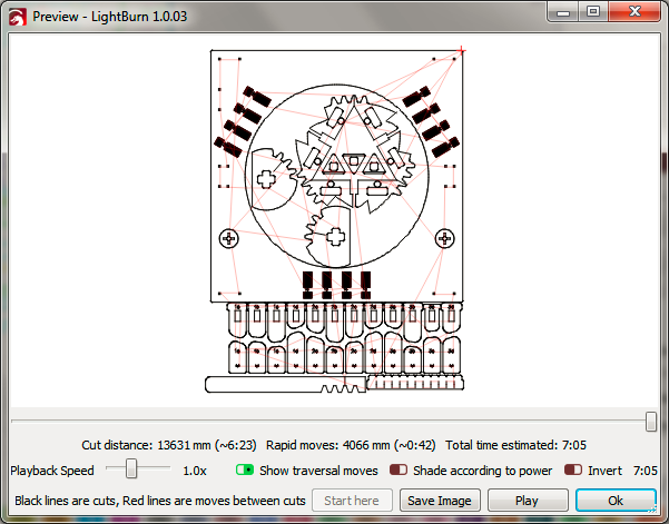
However, the result I’m getting is that identical shapes on the same layer end up with kerf in different directions. In the example image below, the four crosses are all on the same layer. (Note that kerf is intentionally exaggerated here).
I figure that LB is probably trying to do the work for me and I’m trying to do the work for it, but I’ve tried setting the entire file to a single layer with the same result. My guess is that I’ve got shapes nested in a piece of waste material and that’s upsetting LB.
I’ve looked through the optimisation setting and I can’t find a way to turn LB’s interpretation of the useful bits off. Can someone please explain how I’m meant to be doing this?
Yeah, but some of my cutting layouts are big and complex and I’d rather not need to go over them with a fine tooth comb just to see if the software is failing to guess at what I want. I’d rather understand what it’s trying to do so I can work around it, or preferably turn it off.
I can also make it work by changing the large circle to a different layer, rather than the same layer as the crosses, so I’m guessing maybe LB counts line crossings on a particular layer from the outside in? If true, that’s going to be a headache.
What I was hoping to be able to do is say “cut on the inside of this line, cut on the outside of this line” and have the software do as it’s told.
I was referring to the “Kerf offset (mm)” control in the Common tab of the Cut Settings Editor. Positive values claim to be outward and negative values claim to be inward, but that doesn’t seem to be what’s happening.
I would have expected the inward and outward to refer to the shape enclosed by the line.
Aaand I just noticed that the teeth on the gears don’t change shape, even when I exaggerate the kerf compensation on that layer. They should either bulge out if the compensation is what I expect or needlepoint if it’s the opposite. Instead they don’t change shape at all.
I’m confused. Now I’ve got three scenarios - works properly, works backwards and doesn’t work at all. Why would it not work at all?
EDIT: Oops, they’re probably not closed shapes. I should check my own work before ranting. Sorry.
EDIT EDIT: I remember seeing somewhere that LB uses a different linetype (dash-dotted instead of dashed) for closed shapes, but the marquee for all my shapes is the same, whether kerf gets applied to them or not. Is the different linetype selectable somewhere?
Does it select anything it shouldn’t? Kerf is not applied on open shapes, because a line doesn’t have an “inside”, so if shapes are open / disconnected, that would be a likely source of issues.
Alt+J will join / close shapes if the ends are touching.
Makes sense. I just finished joining/closing the shapes that I hadn’t drawn properly (the ones with gear teeth) and they now have kerf applied.
Does Alt+J have a fuzz factor? It would be great if it did a radius 0 fillet rather than a join.
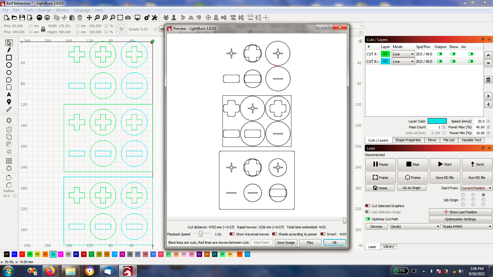
However, my initial problem remains. In the green (layer CUT K+) crosses the kerf seems to be applied differently depending on the level of nesting. The same is true of the 3mm green squares - the outer ones get smaller and the inner ones get bigger.
I won’t mark this as a solution quite yet, but it’s a great workaround. Hopefully either kerf compensation can be fixed or I can be made to understand it. Either way, you’ve got me running again.
Thanks for that. I’m still coming up to speed in LB and I lack some background.
Can you advise, is there any way of telling if an object is closed? If not, that might be a worthwhile feature, particularly on layers where kerf is applied.
(
EDIT:
Oops, Oz already showed me this. Sorry about that. Life is hectic at the moment and I’m not able to give this the headspace it needs).
)
Maybe you can also help with my understanding of kerf compensation. I would have expected any closed line with negative kerf to get smaller and any closed line with positive kerf to get bigger. That’s not the behaviour I observe.
Kerf is applied in one of two ways - Globally, or per-layer, and which one is used depends on whether you have ‘Order by Layer’ enabled in your optimization settings.
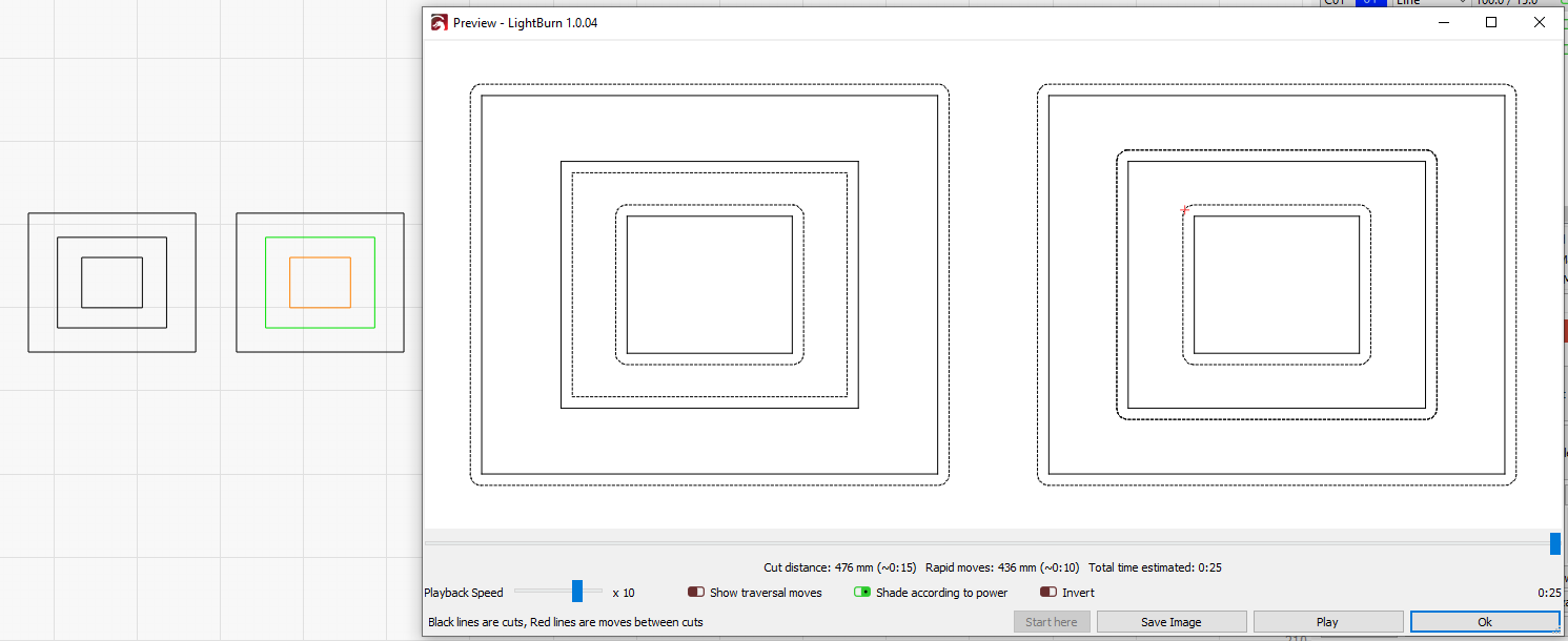
This is with ‘Order by Layer’ enabled - The solid lines are the original shapes, and the dotted lines are the kerf offset versions. The one to pay attention to is the 2nd dotted square, inside the outermost one:
Because the job is processed all at once, instead of per layer, the “inside / outside” order of the shapes is identical to the “all on a single layer” version.
Thanks Oz, but to be honest different optimisation settings changing the final kerf direction does my head in even more.
My problem started when I had to recut a bunch of pieces and I moved some small parts from level 0 nesting to be on a piece of waste wood inside another part. I don’t understand the reason, but pieces that were correctly sized before now didn’t fit because the kerf cut was opposite to that which was required.
Is there an option, or can there be one in a future release, to have inside kerf cut on the inside of a line and outside kerf cut on the outside of a line, irrespective of nesting or processing order?
Okay, lightbulb moment. I assumed I had to do the thinking so I’ve been trying to tell LB what gets cut on the inside and what gets cut on the outside. It turns out that LB knows how to do that perfectly well and all I need to do is stop fighting it.
Everything now has the same direction kerf. Everything now cuts perfectly wherever I put it.
Since we already have to compute inside / outside shapes to be able to cut inner shapes first and for fill grouping, it was trivial to use the same assignments for kerf direction. It works exactly the same as the normal ‘Offset’ operation. I assumed it would be much easier to use it if we didn’t make you manually set all the directions.