Maybe… hence the air cooling inlet on the red dot unit, as Jack also mentioned
might help cool the constant running laser red dot as well…
I have one on order, will let ya know if it is junk ![]()
Maybe… hence the air cooling inlet on the red dot unit, as Jack also mentioned
might help cool the constant running laser red dot as well…
I have one on order, will let ya know if it is junk ![]()
That would make sense: a smaller heatsink with forced airflow. Next step: water cooling. ![]()
curious that with the typical water cooling on CO2 tubes that the business end of the laser would need 'heat sink", but there is a lens that takes the beam brunt output…
Jack mentioned:
So I am not sure if it is for heat dissipation or just ‘good looks’…
This is what I am getting when I need to replace my tube.
Hey Keith…
I looked at those, they are nice but don’t they only come with the tube ?
I could not find them as a separate sell item…
These tubes are manufactured with this on them, and the factory making the tube adjusts them when it’s manufactured. So, you’re not going to find them singularly available.
I was going to do that with mine, but Russ Sadler convinced me not to. I told him on basing on one of his videos. He advised he’s had numerous issues with them not lining up… At least that’s what he told me about a year ago.
I don’t have any led pointers, so it was easy for me to use a lower cost tube without the led…
I’d like to know how it works out when someone gets one.
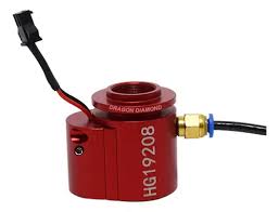
![]()
I have the Red model coming, another week…
I will take pics and report ! ![]()
![]()
I have the typical side mount red dot…
Decided to make a custom 3D printer holder
to better allow it to be positioned…
But hate it.
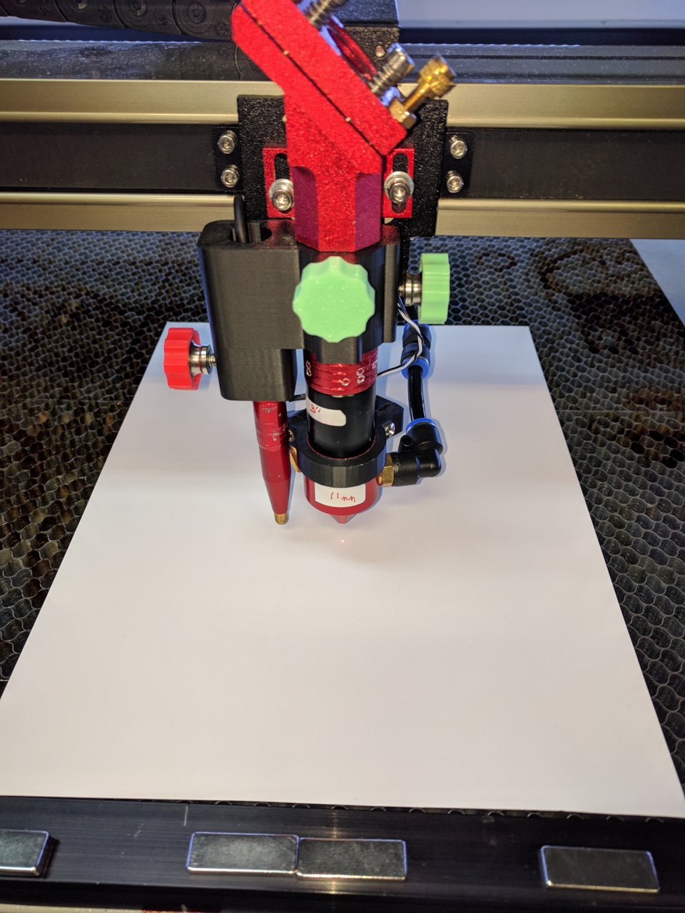
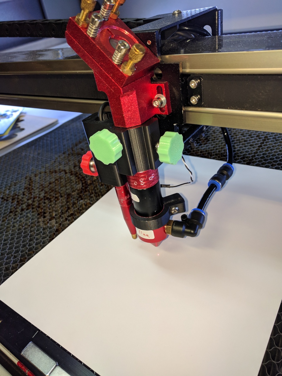
I designed another holder for the autofocus pen and lens tube…
The original Monport Tube had a ring to tighten the split screw to tighten the inserted lens tube. Had to use pliers and put side pressure to tighten and loosen, which put side strain on the vertical lens tube holder, not good over time…
With the autopen and red dot attached to the lens tube assembly it is truely a pain when changing lens.
So I made the housing to go over the outter fixed down tube, threw the retaining ring away…
Drilled a hole in the fixed tube for the Front thumbscrew to pass thru and press tighten onto the inserted lens tube.
The right side Green thumbscrew is just to keep the assembly tightened onto the fixed head tube…
The Red thumbscrew is for the Autofocus pen, adjust the pen height and tighten the thumbscrew.
Once I get rid of the attatched red dot assembly, I can change lens easily with no junk hanging off to deal with.
pretty sure if there was ANY significant loss of power, manufacturers would not be installing these from the factory, including higher end manufacturers such as Epilog, Thunder, AEON, and the likes.
I have no way to measure my Thunder Nova 35/80 or my Pronto 75 150w machine but all documentation for “close enough settings” regardless whether machines have combiner or not, from both manufacturers is pretty spot on
Good to know…thanks
Had not thought about it… but…
I will try some cutting at the higher levels just to push the power supply and see if the ma. rating can actually go to the level it says…
In my case 130w = 35ma.
Dont have the handy Macken Instruments Analog Power meter to measure the output power…( Like Russ does… sweet)
But at least I should be able to measure the ma. thru the tube if the power supply can drive it properly…
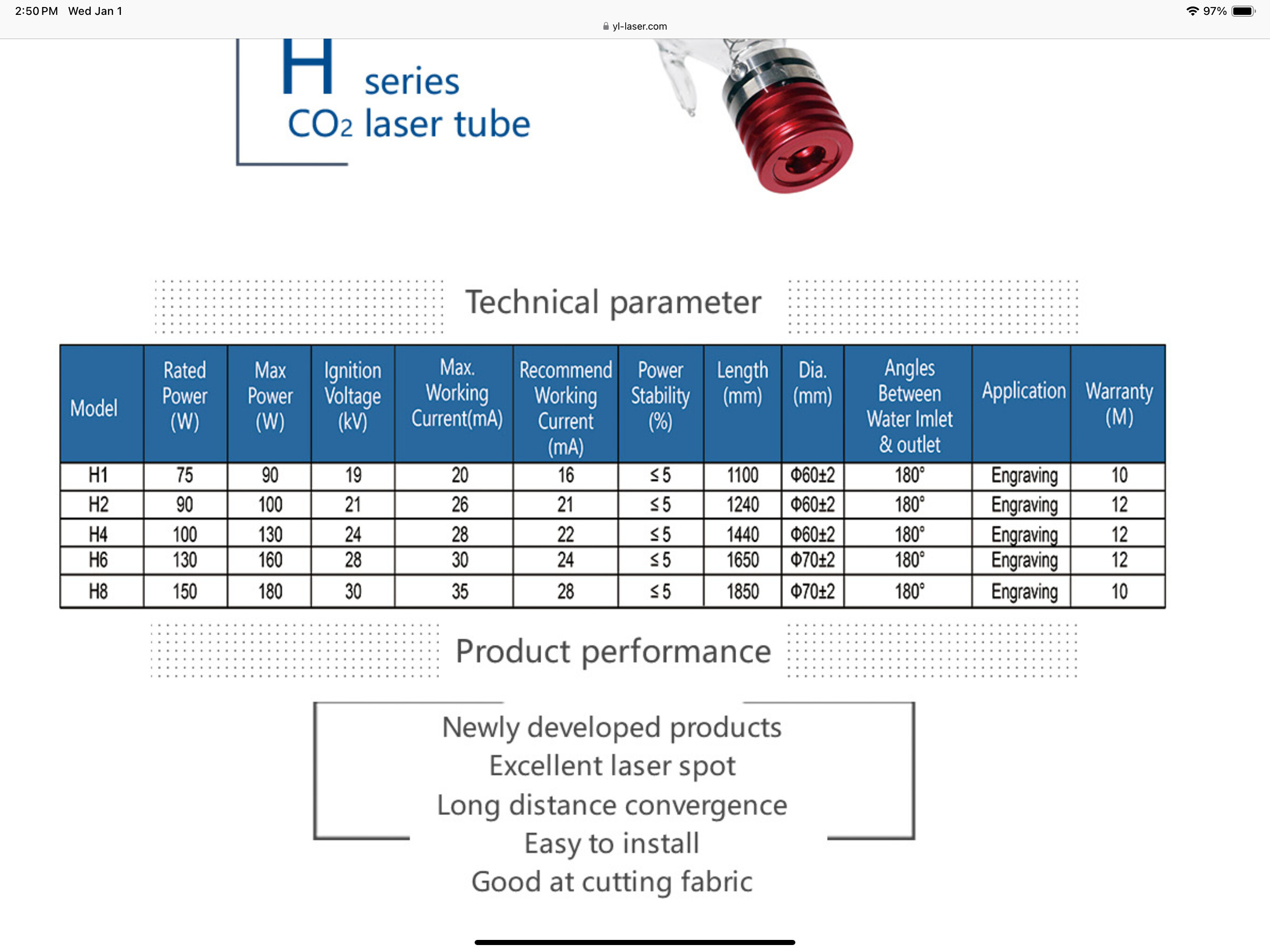
The Yongli 130W tube says (H6) can max out at 160w (130w 160w MAX)
but now I am wondering if they actually have an H4 installed
(100x 130w MAX)
Willl look tomorrow to see… hmmmmmm nice way to save money if so…
The manual also recommends the you not go over 80% long periods to save tube life, as most manual I suspect !
The most I’ve ever pushed it is about 80% = 23ma.
Before I proceed for all the folks that have more experience than I, please
chime in !
Strange that the Yongli chart says MAX working ma = 30ma for the 130w
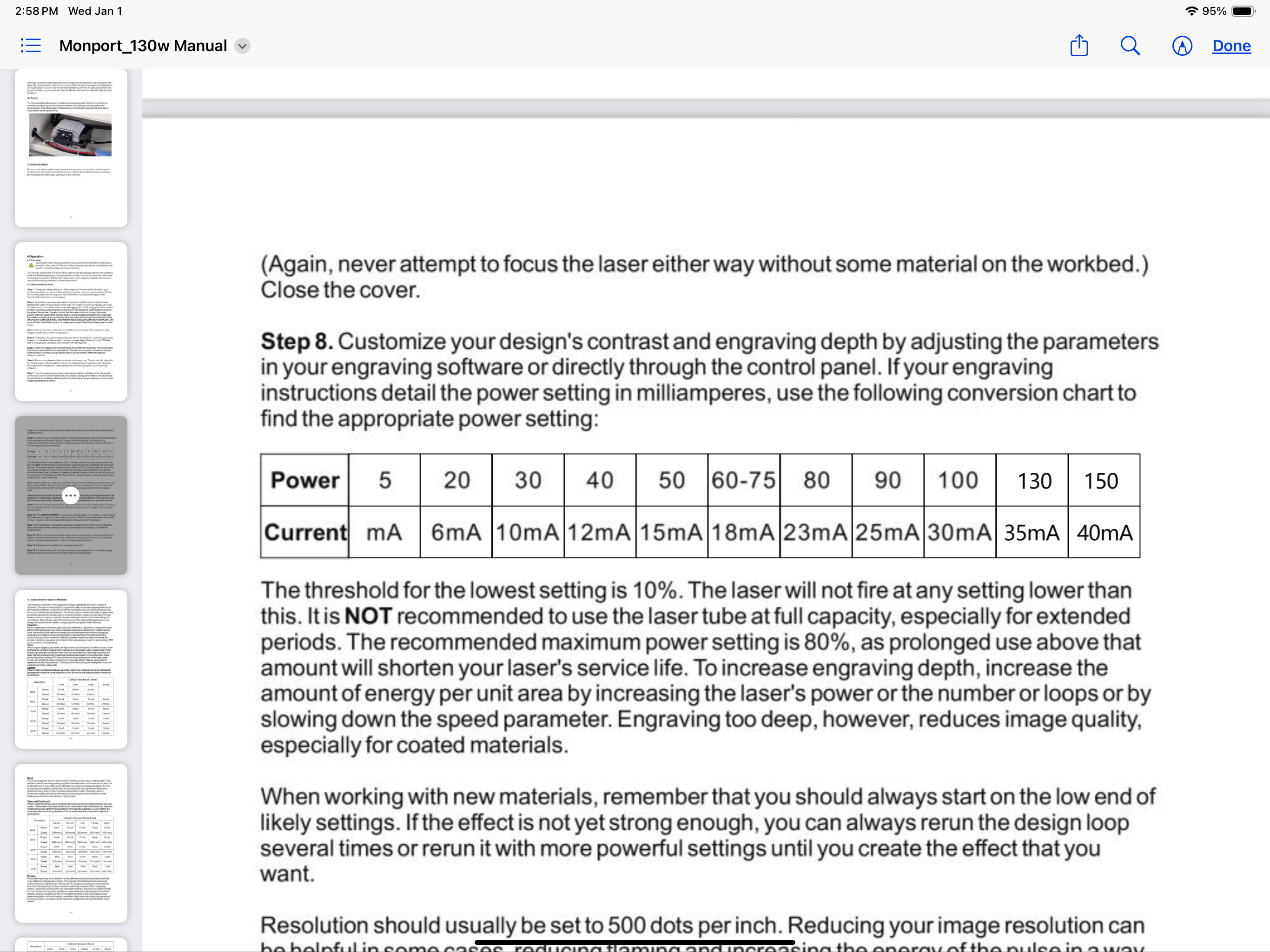
Yet the Monport manual states 130w = 35ma
Head scratching…
(YONGLI TUBE CHART)
(MONPORT 130W MANUAL)
Based on two power supplies for my machine and a few experiences in discussions around here, it’s likely:
I got myself a YongLi HLP-200B power meter as a Christmas present and, while I don’t have any definite advice yet, this graph summarizes the tube power vs PWM power setting:
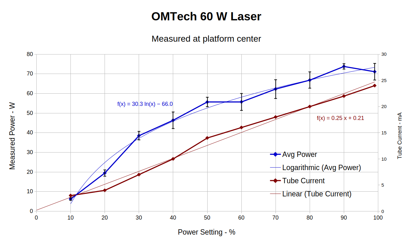
The brown curve (right Y axis scale) is the tube current, as reported on the HV supply’s digital meter, and is pretty much linear. The tube arrived with no current spec, other than a scrawled “21 mA” corresponding to “60 W”, so the supply is overcooking the tube above 80%.
The blue curve (left Y axis scale) is the measured beam power as the average of five pulses, with the error bars at ±1 std dev. With that much windage, the logarithmic curve fit seems reasonable and clearly shows the decreasing oomph at higher current / power settings.
So not exceeding 80% keeps the tube current at a reasonable level, while exceeding 80% doesn’t buy you much at all.
Good stuff Ed…
Down side to being an engineer, can’t keep your hands outta stuff…![]()
I will set the power to 100% ck out the ma and get a better feel for the tube actuality…
Without a power meter, it’s all blind faith anyway…
Sooooo… give us a report on your new toy ![]()
The Macken power meter is pretty nice, and pricey…
TL;DR: the HLP-200B is a bit over $200 on Amazon, positioning it in an invisible laser beam is touchy, and the measurements seem plausible.
More details on my blog, with more to come as I get further down the to-do list:
Because my arms aren’t long enough to hold the meter at the laser exit and push the Pulse button on the controller:
Beam combiners ARE indeed lossy. They generally don’t absorb power, most of the loss is what it reflects at 90 deg.
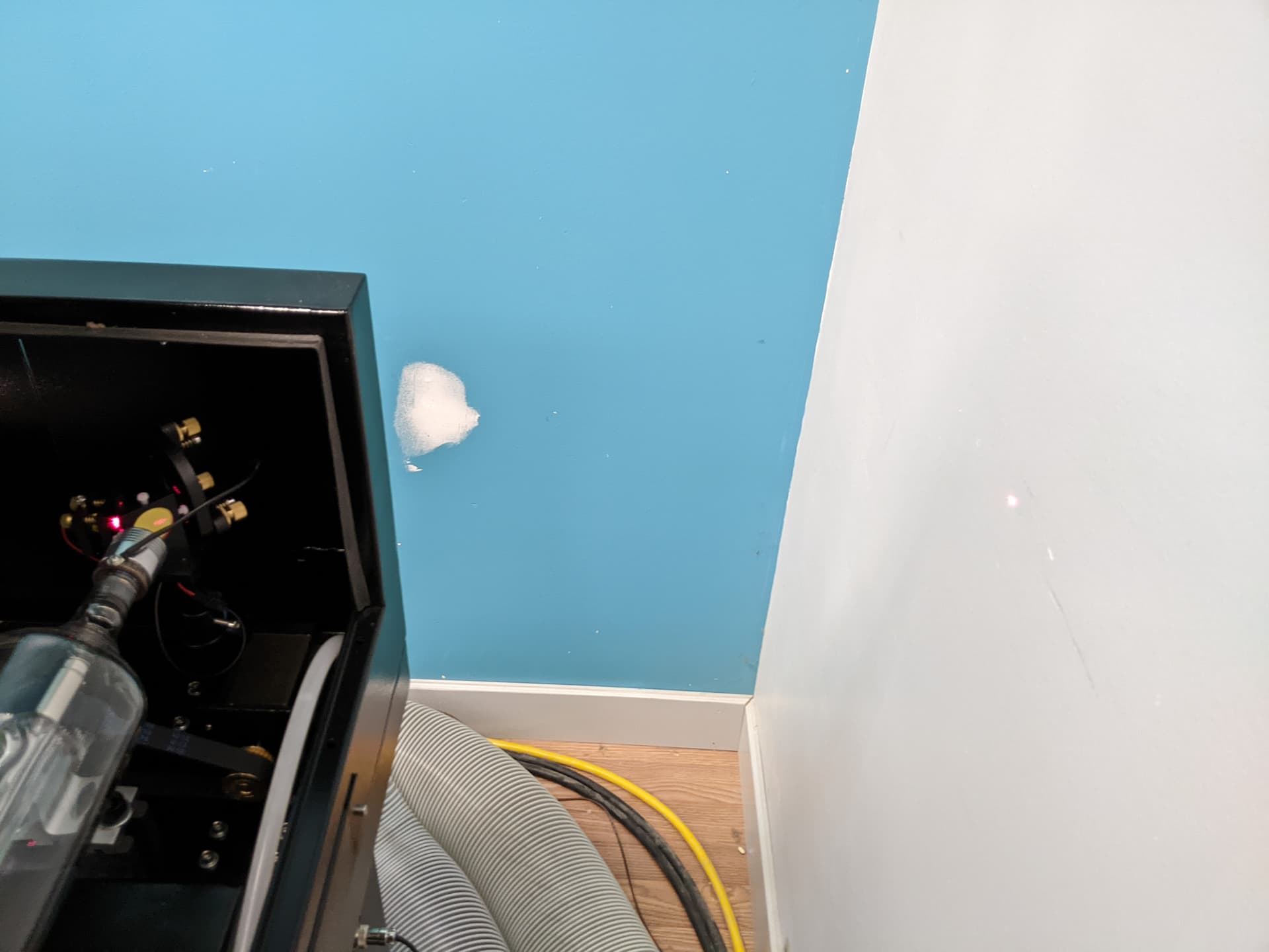
The more infamous case is where they orient the combiner so that 90deg beam path doesn’t have any stop on it when the hatch is open. You NEED a beam stop of black anodized aluminum for the reflected path, as shown in thelmuth’s photo.
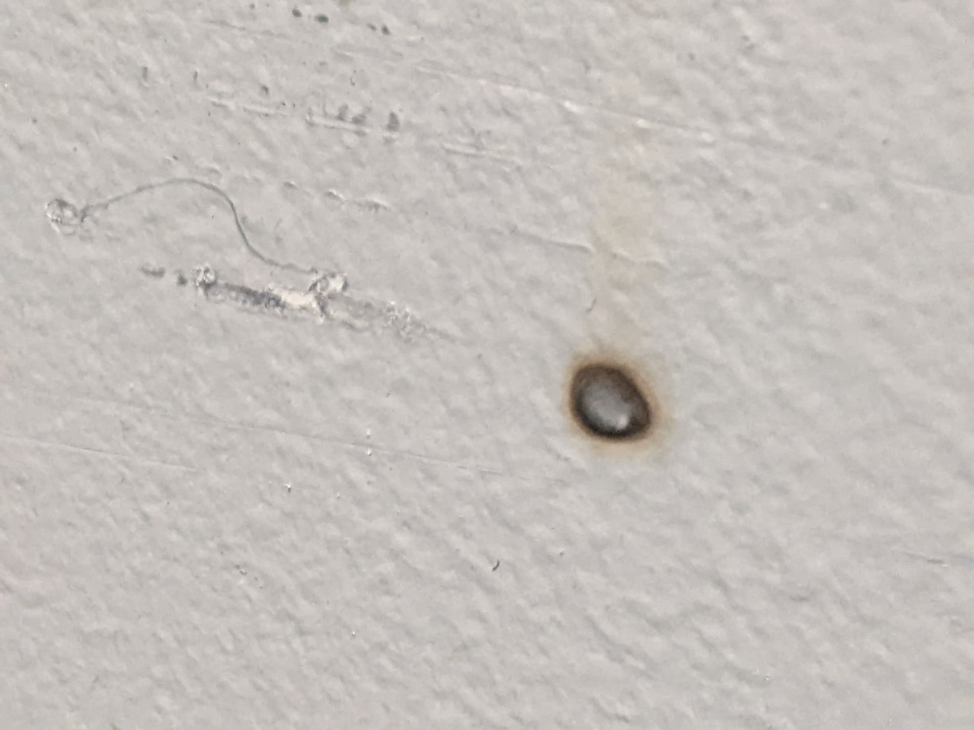
The Laguna Shopsmart EX (which is a rebranded G. Weike L1390) is infamous for that. It actually burned a hole in the wall with the hatch open.
Someone else brought this up on the Laguna Tools Facebook group and we swapped pics of burn marks.
Anyhow, yes, there is some wattage loss. I still believe in their necessity, at least for our Makerspace. Too many people would have a hard time working out alignment without a colinear red dot. It also greatly simplifies aligning the machine and esp that #3 mirror.
What American Photonics points out is that it doesn’t take much mechanical pressure at all to stress these optics. Often they mount these with nylon screws- if you use them, go for the absolute min force to hold it in place.
The loss in these upstream pass-through optics is not just in absorption and reflection. Any “scattering” of the beam is loss. That is energy which still goes downstream, but deflected at some angle and generally that energy won’t make it to the final lens and onto the table. Rather, it a general haze of very low energy density around the 6mm or so of the actual beam. Most of it will be reflected by the #1 mirror but fall outside #2.
This can easily go overlooked. Even with my Coherent thermopile meter that gives a digital readout of power in real time, I didn’t see the problem when I placed the sensor between #1 and #2 because tall that scattered energy still made it onto the meter. But then I put the meter under the head and saw a substantially lower number, which was a real head-scratcher because nothing was getting hot and it seemed like energy was just going nowhere.

Oh and FYI I did try replacing Laguna/G. Weike’s stock beam combiner with an American Photonics. It may have been better, but still burns a hole in the wall. I should try to measure the wattage being lost on it, I’ve got the meter.
Hey, nice beam profile!
Bonus: Winning entry in the “Why laser eye safety must always be a thing” contest.
The wall was a good beam dump. Your navel would probably work just as well, except for that shiny belt buckle getting in the way. ![]()
If you can set the analog DC current at the laser HVPS, you definitely should!
If you have an MYJG HVPS, it doesn’t have an analog pot on the supply itself, but they sell these. It’s crazy they don’t include this $9 part with the machine.
So, like for a “130W tube 160W peak” Reci W6, I asked Reci what they recommend for long-life continuous current. I got an answer of 26ma or 28ma for the W6, depending on who you ask. I see Yongli wants 24ma on their H6 tube which is an equivalent. It’s a subjective number anyhow.
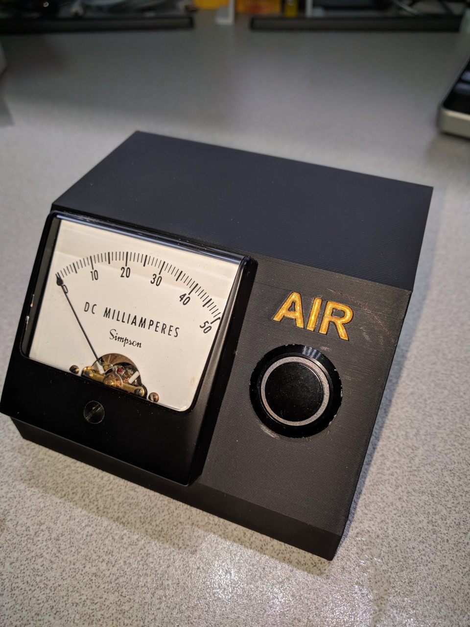
What I recommend is you fire the laser at 100% and adjust the current to 26mA. Ideally I prefer an analog mechanical meter movement over the digital readout, I believe the analog meter is more accurate, but do what you prefer.
Then you can use settings at “100% power” which makes life a lot simpler. It’s the net DC current that wears the tube prematurely, and you’ve got that limit set by the hardware.
Without an adjustment box like that on the HVPS, “100% power” can create a wide range of currents depending on the supply and how it feels that day. It will be substantially over 26mA though. Is 70% Max Power the right limit? 80%? Who knows. If you have an analog meter (which you definitely should) you can trial-and-error to find what PWM of max power gets you 26mA.
What I wish I had real info on is the actual relationship of tube life vs current, and no one has ever sat down with a bunch of tubes and run each one at a different constant current until it fades. There’s no data at all. Even if you bought 12 tubes and ran them to death at 12 currents, that probably doesn’t mean much because the actual tube output and ultimate life span are wildly inconsistent. They claim 10K hrs but that’s absurdly more than most people actually get out of a tube. I’d wanna run at least 5 tubes at each current and take the average hrs to death to even start to have confidence in the numbers.
Now, hypothetical case- say a tube would last 3000 hrs at 26mA, but would last 6000 hrs at 13mA. But that’s half the wattage out of the tube that whole time. If you need 2 hours to do 10 Christmas ornaments at 26mA, you’re going to need 4 hrs at 13mA. This hypothetical case would actually be ZERO gains in tube life in terms of number of Christmas ornaments you can get out of a tube- the second case is just where someone wasted another 3000 hrs of their life babysitting a machine to get thoe jobs done for no reason at all.
So really a tube life needs to be thought of in output watt-hrs. e.g. I run the tube to whatever makes 100W of output power and it works for 3000 hrs, that’s 300KW-hrs of life. What we’re looking for is a nonlinearity, where turning up the actual useful output power by another 10% accelerates the tube decline by more than 10% so the watt-hrs figure starts going down.
I wish I could find data on that. But I’ve never seen even poorly substantiated claims on how that works. I did try changing the laser from 26mA to like 32mA for a brief power test- since this is a 23% increase in current, my rough expectation would be a 23% increase in output power. I don’t recall the actual numbers but it was a much lower increase in output power than that. I wouldn’t even call the increase significant. I would bet for sure that 32mA would degrade the tube faster in a really significant way, though.
I do have an analog meter for the 100% testing…
All good info…
Especially the laser beam ‘wall’ stop…grin
Tomorrow is the test…
This isn’t a good idea for setting these up.
You should set power to 50% and set the current limit to 1/2 of the target current. This leaves little chance of running more than it’s max through the tube by accident.
You could do a current vs wattage graph if you want to dial it in. The maximum output sometimes occurs at a lower than maximum current rating. Then you can set your percent power either current or wattage.
These are negative resistance devices.
![]()
This is a better plan…
Had not considered the top end may be set wrong…
New plan:
Step the power up in increments, ie. 50/60/70… etc
and ck the .ma out and chart it…
Thanks Jack ![]()