Beam Combiner Downside?

Ok did my tests this morning…

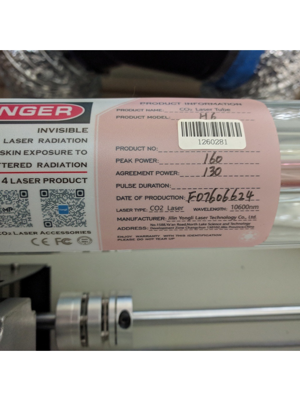
I was pleased to see Monport actually put a H6 130W tube in this unit, have to say
I am very impressed with the overall design and parts, especially the workmanship on the inside, wiring etc… all done with care !

Now the testing:

Started at 50%:

50% 18ma
60% 22.5a
70% 26ma
80% 30ma
90% 34ma
100% 37.25ma

I am really interested in hearing the comments from the experience folks on these numbers…

Especially as they seem HIGH on the upper end…
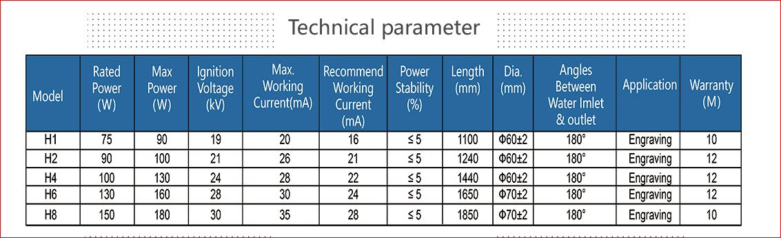
As the tech parameter states MAX Working ma to be 30ma.

Interestingly enough in the Monport Manual they say Do NOT run the laser
over 80%… hmmmm I see their thinking…

But in the Yongli Chart the recommended working ma is 24ma…
Which pushes the over power chart to around 68%…
BUT that is if the testing parameters are wrong, which seems to be the case.
I really need a Power Meter at this point…
Ed, you ever get down to Florida :slight_smile:

Maybe I should go into the settings and bump the MAX end down to 80% just to be safe…

But glad to see it is the H6 tube with the high end being 160wPeak.

YONGLI CHART ON THEIR TUBES

1 Like

Is it marked? Do you have access to a watt meter?

The instructions were to set it for 50% of max. This is 50% of 36mA, so it’s not far out of range. Keep in mind that these are negative resistance devices and do not obey Ohms law.


Usually tubes have two limits, one is operational maximum, the other is absolute maximum. Speaking to someone who should know, he advised that you can run it to operation maximum without damage, but over that you actively start damaging the gas mixture. I’ve used this chart since I’ve started lasing stuff and find it pretty close. If the manufacturer advises a maximum current, I wouldn’t run it over that, except for short periods.

:smile_cat:

Do you have a watt meter for this machine?

It would be nice to know if the 24mA operating current produces the desired 130W and if the 30mA produced the 160W.

Under no circumstances would I run it over 30mA.

:smile_cat:

Yes it is marked, look at the earlier picture of the tube… (above)

No, dont have a watt meter ‘yet’…

But I like Ed’s digital unit seems to respond faster than the thermometer types.
Still deciding…

FWIW, I built and use this for my K40 laser cutter and it works great. It goes after mirror #1 and fits in the hole in the chassis after mirror #1 on its way to mirror #2.

I’ve read there was some power degradation but really didn’t notice any but there has to be since the reflection is not 100% perfect.

1 Like

Doug… nice design…
I always appreciate the 3D designs…
Hard to live without them anymore…

1 Like

Ed… Read your blog on the Power meter, good write up…
Not crazy about the 6 sec reading before turning off… cripes

but did alot of looking today and finally ordered the
HLP-200B …
Really need to get a handle on this 37ma at 100% power (130W)

I know the target is only 20mm dia. but how long did it take to get a reading,
assuming it is power percentage dependent!
Say when you did full 100% on your 60W laser…
You mentioned it will beep (albeit hard to hear) .

The thermometer types say 30sec exposure time for a reading…
This should be a bit faster…

Regardless of the power level, the measurement starts when the beam lights up, runs for about 10 s, and ends with a beep. You then have six seconds to extricate the meter, flip it around, and memorize the reading before the shutdown beep.

The shot-to-shot variation still puzzles me. I watched the tube current on the HV power supply’s digital meter while firing into a trap. At 25% PWM the current is stable at 6 mA with occasional excursions to 5 mA, which might be ±10% around a little over 6 mA.

Six successive measurements at the tube exit vary from 26.9 W to 35.5 W, with an average of 30.7 W: -13% to +16%. That seems larger than the current variation can account for, but I may be expecting entirely too much from one significant digit. :jigsaw:

I understand the idea of measurement at tube exit…

But is it possible that the meter may get overwhelmed that close ?
ie. the sensor may need to be moved around to saturate the sense spot better ?

Maybe after say mirror two (entry into the laser head tube)
you might get a more consistent measurement ?
But still using the movement technique ?

This is puzzling, I can see alot of time being taken when the meter arrives here!

Truely a work in process… continuous!

It’s a 200 W meter, so I expect it can handle 15% of that without breaking a sweat. Well, it does turn into a handwarmer after a while, but you know what I mean.

Besides, we’re talking a laser beam, so it’s about the same diameter from the tube exit to the top of the focus lens. Distance doesn’t make much difference, apart from path length losses.

The entire front surface (and the back surface, too) is one aluminum slab, so there’s no distinct “sensor” other than the concentric ridges milled around the center point. Given that the beam is invisible, I have no idea where it’s actually hitting, other than that it’s in the ridged area, which better be good enough: they tell you to aim for the middle while hand-holding it.

The variations seem about the same regardless of whether I use the fixture or hold it.

Thanks…
I guess for an extra $$$$$ we could get better accuracy, but this should provide some data that is usefull anyway… :face_with_raised_eyebrow:

Wait… did you say the case is all metal ? not just the target area ?
Looks like plastic…

It’s their way of enforcing the cooldown interval: when it gets too hot to hold, stop holding it. :grin:

I have the uneasy feeling the shot-to-shot variation comes from the laser tube / power supply, not the meter. I’ve been assuming the current stayed stable during long pulses, which may not be how it works.

Directly measuring the tube current requires unpacking a few more boxes and conjuring more outlets on the Electronics Bench, but the optical output (cyan) tracks the tube current (green) quite nicely:

That’s at 90% PWM and the tube evidently takes a few milliseconds to get up to speed and calm down.

Having just touched the drawer with those photodiodes (while looking for something else), that might produce comparative numbers with less hassle. Gotta wear warmer socks in the basement, though.

1 Like

I suspect it’s the tube not acting the same with limited current. The beam factor gets better as you increase the power. I’m sure that’s why many of the vendors want you to test it at 100% (or high power), much better chance of it showing little to no sign of a mode change. It’s more likely that a TEM00 can be attained at higher current values.

This is one reason that RF machines have a better beam factor, they are on 100% or off, nothing in the middle, unlike a glass tube, as they are digital.

I abused the :poop: out of my old tube, after I got a new tube ordered. I ran it at 100% for quite a while… Got better results, but it was impossible to get a good mark to see the power distribution at m1.

:smile_cat:

Ed…
That is a 10% start up time for the 90%PWM…
Seems a bit excessive, Question is: Is the power supply contributing to the
down sizing of power to the tube to fire efficiently…
I would expect some start up time for the PWM but the ringing looks excessive 2.2-2.4ms(per your scale), maybe some switching ps guru can provide more clarity…
Is this normal for even high end switchers?
or are these co2 ps’ mostly $$$ conservative designs ?
Just an observation.

With a Ruida, pwm response time is generally considered insignificant as the pwm runs as soon as you start a layer and continues for the execution life of the layer. Unlike an LED or RF laser.

The only exception is grayscale which generates massive amounts of data as the power of the tube is varied as it does it’s work…


The lps and tube are a pair, so to speak… There are many thing the lps can do that can effect tube operation, but generally we don’t see that many failing lps.

Many replace the lps when they replace a tube, most not sure if it’s the tube or the lps or just feel better doing that. I prefer to isolate it to the optimum replaceable unit (ORU). When my tube went out of TEM00 mode, I just replaced the tube and still have my original lps.


What does make a difference is the time it takes for the Ruida to signal the lps to lase. From the signal to lase to when the hv gets high enough to the tubes trigger voltage.

This is commonly referred to as response time and is usually specified as <=1mS to reach a certain voltage. So 1mS is worst case, knowing the Chinese. I’d be surprised if lots of these make that, but we’ll take that as a worst case example.

1mS is 1/1,000th of a second, so a machine running 1000mm/s is only able to turn the tube on/off every mm. The best resolution you can expect from that scenario would be 24.5dpi or an interval of 1.

At 500mm/s it doubles to 50.8dpi or a 0.5mm interval and at 250mm/s you can go for the high detail of 101.6dpi or an interval of 0.250mm.

The beam size of most of these hobby co2 lasers are about 0.20mm, which limits the maximum resolution you can possibly obtain.


You can see where speed isn’t really on your side with these… Mine will run 1650mm/s, but it’s pretty much academic as you can’t really use if for anything.

What pays off is being able to increase the acceleration, so it spends less time getting to the next scan. My acceleration for the X axes is 45,000mm/s^2.

This is a 40,000mm/s^2 acceleration compared to a 6,000mm/s^2 acceleration. Note the time difference and a smaller over scan.

Good luck

:smile_cat:

Compared to what? :grin:

AFAICT, it’s not “ringing” in the sense of damped oscillation. Instead, it’s the power supply desperately trying to gain control over the initial negative-resistance conduction along a meter of gas. The peak current in each spike is spectacularly high, but the overall energy isn’t all that much and seems to average out to the right answer.

It’s not really a switching power supply in the usual sense, because it’s attempting to regulate the average current through the tube. Anecdotal evidence suggests spendy lasers from reputable companies have better HV supplies less prone to the random dot problem, so they may well have much better overall regulation.

There’s basically no schematic of a contemporary CO₂ supply to be found, although various reverse-engineered K40-style schematics pop up from time to time.

I crawled through the tube current and response time things a while ago, discovering that the PWM demodulation filter has a cutoff around 200 Hz. A 100 Hz PWM carrier (cyan) (in contrast to the usual 20 kHz) produces current (green) that looks as much like a square wave as you’ll get:

If you squint, the rise & fall times are maybe 2 ms.

The digital Enable signal (magenta) is faster, but the tube current still isn’t the tidy DC current you might expect from a milliammeter on the cathode lead:

It’s not neatly organized, but this will get you started:

More than anybody cares to know, I’d say. :grin:

This is good stuff Ed, you spent some time getting these reading…
very nice job…
I’ll have to spend some time digesting this next week…

Heading to Chicago on a job soon, so maybe a little light reading in the evenings is in my future :slight_smile:

I suspect this is normal because the period is long enough for the lps to view it as each cycle of the pwm being a different pwm cycle. So it has time to turn on and off at the 100hZ frequency. Remember the period is only 10 mS compared to the 20kHz period of 50 micro seconds. Even at 1kHz, the period is 1mS.

:smile_cat:

That’s what I was exploring, varying the PWM carrier over an absurd range. On the very low end, well below the demodulation filter cutoff, it behaves like a square-wave analog signal, so the step response gives an indication of the filter / supply risetime.

Which was part of realizing the PWM signal at normal frequencies does not directly modulate the tube, contrary to everything I thought I knew up to that point. :astonished:

An RF metal tube turns the modulation on/off in a digital manner as it’s a digital device… this is why there are different effects when an RF lasers pwm period is changed.

Also, most of the lower cost co2 type machines, like the K40, sets the lps limit current to a manual value, then enables and disables the laser. Driving it like a solid state device. Even most upgrades, except Monport, do the same thing.

:smile_cat: