Hi
I have been having issue when using Bi-directional fill on engravings -
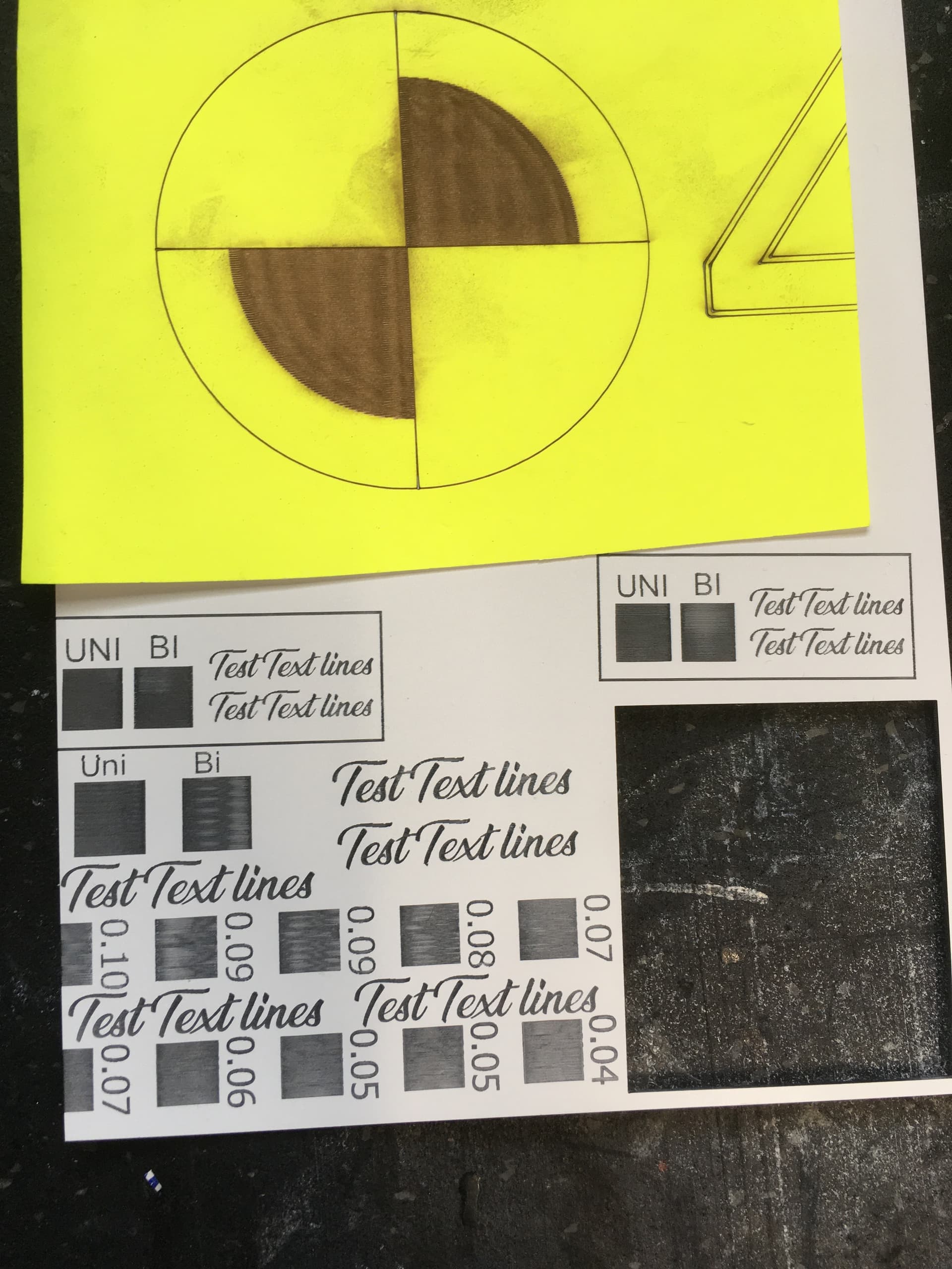
Current using lightburn 1.7.04( was present with previous versions of lightburn) the lines are not parallel to each other. Picture attached shows two fill squares next to each other in the same job. the one on the left is uni-directional and the right is bi-directional which the lines vary.
doing the scan horizontal (along the X Axis). I have seen a number of post with similar issue most stating mechanical backlash etc issue but yet to see if anyone has confirmed a solution.
LPI or speed does not change to result, Photo was at 100LPI at 500 speed as easier to see the varying lines in the scan with Bi-directional.
i have a ruida RDLC Ver7.10.08 firmware on the controller 100watt tube - now the interesting part is it Does it with the rotary as well so hopefully ruling out the Y motor and belts etc
I have checked all rollers and belts are secured and firmly tightened.
So don’t know what else to check.
For your reading pleasure.
1 Like
The misaligned ends of the lines parallel to the scan suggests you should measure the offsets at a variety of speeds, then fill in the Scanning Offset Adjustment table. The table entries are half the measured offsets.
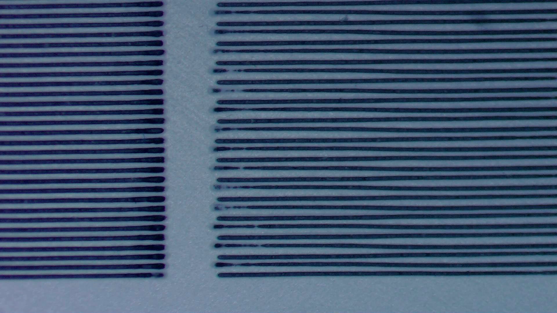
A closer look is informative:

The upper red line shows a right-to-left scan and the lower red line shows a left-to-right scan.
At 100 DPI the lines are 0.254 mm apart and the line width (roughly the spot size) is half that; 0.12 mm is a pretty tight spot for a 100 W laser.
The lower red line suggests the maximum offset in the Y direction is a little more than half the spot size, perhaps 0.10 mm.
The small error in the Y direction smoothly reduces after about 6 mm of travel along the Y axis = 12 ms at 500 mm/s. The fact that it’s smooth, not a wobble, suggests the belt tension is fine, nothing is loose, nothing is shaking, and the mechanism is fine.
You can try relaxing the belt tension by a smidge using the tension screws on the pulley opposite the drive pulleys (typically in the front of the Y axis), but not by more than half a turn at a time. If the lines start wobbling, that’s too loose.
For a large CO₂ laser, that’s about as good as you’re going to get.
The spotted sections of the left-to-right lines suggest the tube takes 2 mm = 4 ms to stabilize after turning on, which may be due to a low power setting in that LightBurn layer.
If that results in visible defects, cutting the engraving speed in half to 250 mm/s will reduce the startup distance to 1 mm, but at about half the power for about the same burn intensity, which may cause other defects.
Fiddling around Adjusting the power and speed while looking at those lines may improve the overall result, but it’ll probably be a minor change.
Assuming the scan is parallel to the X axis, the rotary will probably reduce the initial offset. If it’s a roller, the mug / sippy cup / whatever will likely wobble a bit after each motion, so you may see similar offsets.
The tube startup time will remain about the same.
Regrettably, doing the Happy Dance seems to distract many folks from a return visit to say “Fixed it!”. ![]()
2 Likes
Thanks Ednisley for that detailed explanation and Tim for the link to the documentation.
The machine has the scan offset values provided from the manufacturer (which might still do with a little tweaking). From the info you guys have provide me has sent me looking into the settings of the machine and might be onto something…
As this is my second machine i was able to compare the settings from my old machine (which i no longer have) to the new one (with of course obvious differences) and came across this …
Refer to Max Acceleration value…
I Know servo motors can be fast but holy C#$% compared to my old stepper motor machine which is only 3000mm /S.
is 25,000mm /S a realistic value for servo drive acceleration??
So before i go and do the happy dance i will need to confirm this is the issue BUT! (there’s always a but) my controller appears to be locked by the manufacturer and the default password does not work.
So i will need to wait for them to get back to me with the password and hopefully a correct value (someone put in one too many 0s?)
I will return with the outcome shortly either way.
Thanks for your time - much appreciated.
On my machine (and apparently many others), you just change a value in the LightBurn Vendor Settings and it’s done. Is that not how your controller behaves?
The various passwords applied directly in the controller protect changes to settings and functions with catastrophic outcomes. So far, I haven’t had need of any passwords.
In particular, do not trigger any of the Reset operations, because they can apparently blow away settings inaccessible to LightBurn and there is no way back.
Seems aggressive to me, too.
However, it’s limited by the overall acceleration values in the Idle, Cut, and Engrave sections near the top of that Machine Settings window, so it may be one of those numbers never coming into play because it’s capped elsewhere.
Of course, those values may be absurdly large, too. ![]()
We’ve had some issues with the timing between servos and steppers.
I know a bit about them, but not enough to give advice.
I don’t have servos and won’t every have servos on a glass tube co2, just isn’t worth it.
Try this thread and/or just search for servo… on the site.
Good luck
![]()
Hi Ednisley
Just an update - yes i am very cautious about changing any machine settings and make sure i have a backup. Now in the machine setting there are two sections for axis settings and some duplicated under Vendor settings - when i tried to change the acceleration under vendor settings, it reports save successful but when i go back and read - the old settings are back again. My understanding of the vendor settings is basically a hard limit of the controller so desspite what the software trys to command the controller will not allow it to exceed its limit.
Anyhow i am able to change and save the the setting (not under vendor settings)
i have done several test - trying to keep everything consistant so i have a file with two fill boxes next to each other one Uni directional (left) and Bi-Directional (on the right) Same settings on each only on differnt layers as part of the same job - same file same setting in each test only thing changing is the X acceleration value - as i slow donw the acceleration the lines tend to improve to the point wher at 3000mm/S the lines are parallel. what gets me is in all the test the Uni directional lines a almost perfect every time

Above this is at 25000mm/S

above now at 3000mm/S

The test sheet you can see al little of the artifact on the right rectangle (engrave a little uneven) when acceleration is 10000mm/S.
Testing to continue…
It’d be helpful to know the Ruida controller, which should be printed on the main box inside the electronics bay: RDC6442 / RDC6445 / KT332N.
That will let us poke at the manual, which is often misleading, and maybe get a little further.
That’s true of all the controller settings, which often trips folks up. The controller determines how fast each motor will spin based on the desired speed, the angle of the vector with respect to the axes, the type of motion (move / vector / engrave), and the various speed limits. You can tell LightBurn to run at any speed you want, but the controller sets the actual speeds.
A recent discussion involved stepper drivers with exotic configuration switches, one of which had been bumped out of position:

Upload pictures of the servo drivers in your machine so we can read the model numbers, find the manuals, and see if something weird is going on.
A nitpicky point of order:
- Speed has units of
mm/s - Acceleration has units of
mm/s², sometimes written asmm/s^2
In a paragraph discussing both speeds & accelerations, hanging the proper units on the numbers helps everybody understand what’s going on.
While I’m pretty sure you mean 3000 mm/s² and 25000 mm/s² as accelerations, we have had discussions where folks sincerely believed because they set the LightBurn layer to a speed of (say) 25000 mm/s the machine would actually do that. ![]()
1 Like
I think something is loose. If you look at the lines one set is varying as it moves.
Don’t know if the areas you have marked out is an optical illusion that one of the sets of lines are straight.
If it’s doing better with a faster acceleration, it could have something to do with ringing with whatever is loose…
I don’t know how far he can push his machine. With the head and stripped X axes, my X acceleration is set to about 45,000mm/s^2.
With steppers, you can increase the acceleration until it misses steps then lower it about 10%… don’t know how you’d do this with a servo.
How fast are you attempting to run? Is the 500mm/s value one you use?
![]()
Aye, and those seem to be the ones where the head has just moved in Y from the previous lines. The straight ones are where it’s coming in from the far end of the line and has long since settled down.
It could be the position not settling quickly after a step position change, so we’re seeing servo feedback in action. If the driver has a filter time constant / bandwidth setting and it’s set for more than a few ms / less than a few kHz, then maybe that’s what’s going on.
None of those driver settings would be exposed to the controller, unless the controller is specifically set up for servo motors; some digging is in order there, too.
Or I could be wrong again. ![]()
Hi
Valid point i will ensure i state the correct units of measure in the future.
The controller is a Ruida RDC6442G-LY-1G-ULimit(EC)
The motor Driver is CL1-507-3LS
Now the X and Y drivers (both have the same settings as show) and motors are the same and i have replaced the Y motor due to a motor whine noise (2 ~3KHz) which comes goes (different issue).
fill engrave test.lbrn2 (49.1 KB)
Attached is the test file i have been using - i have just added more text (shown in previous photo) to keep track of results of test.
Now correct me if im wrong but (mechanically speaking) the Uni directional engrave and Bi Directional engrave are basically the same the main difference would be when the laser fires and also delay in the laser fire is applied in bi direction. is there any difference (mechanical movements / delays) between the Uni direction and Bi direction? As far as i can see there must be something else applied to the movements in Bi Direction mode as uni direction is fine each time.
Now we can see that changing the X Acceleration value affects the wobble in the lines 3000 mm/S^2 ![]() best result but stupidly slow. to throw a spanner in the works - Previously before the test and changing the Acceleration value (originally at 25000mm/S^2) and before i knew what was causing the artifacts in the engraves. I had tried various engrave speeds and line intervals to get a decent engrave on the 2 ply material but could not get a result as good as my old laser. have tried 150mmS to 600mmS
best result but stupidly slow. to throw a spanner in the works - Previously before the test and changing the Acceleration value (originally at 25000mm/S^2) and before i knew what was causing the artifacts in the engraves. I had tried various engrave speeds and line intervals to get a decent engrave on the 2 ply material but could not get a result as good as my old laser. have tried 150mmS to 600mmS
The engrave speed setting of 500mm/s and power of 16% and 100 LPI was values chosen to make it easier see what is going on with the 2 ply material and keeping them constant as a reference.
I will try to do a test at different engrave speeds and keep the X Acceleration value the same at the original 25000mmS^2 (may be ugly as it will be hard to reduce the speed and reduce the power not to blow holes on the material). past engraves didn’t matter what speed i did it at - they were pretty ordinary.
Here are the results from the test with the X Acceleration back at 20000mmS^2 and a range of engrave speeds
500mmS 100LPI 16/10% power.

250mmS 100LPI 16/10% power.
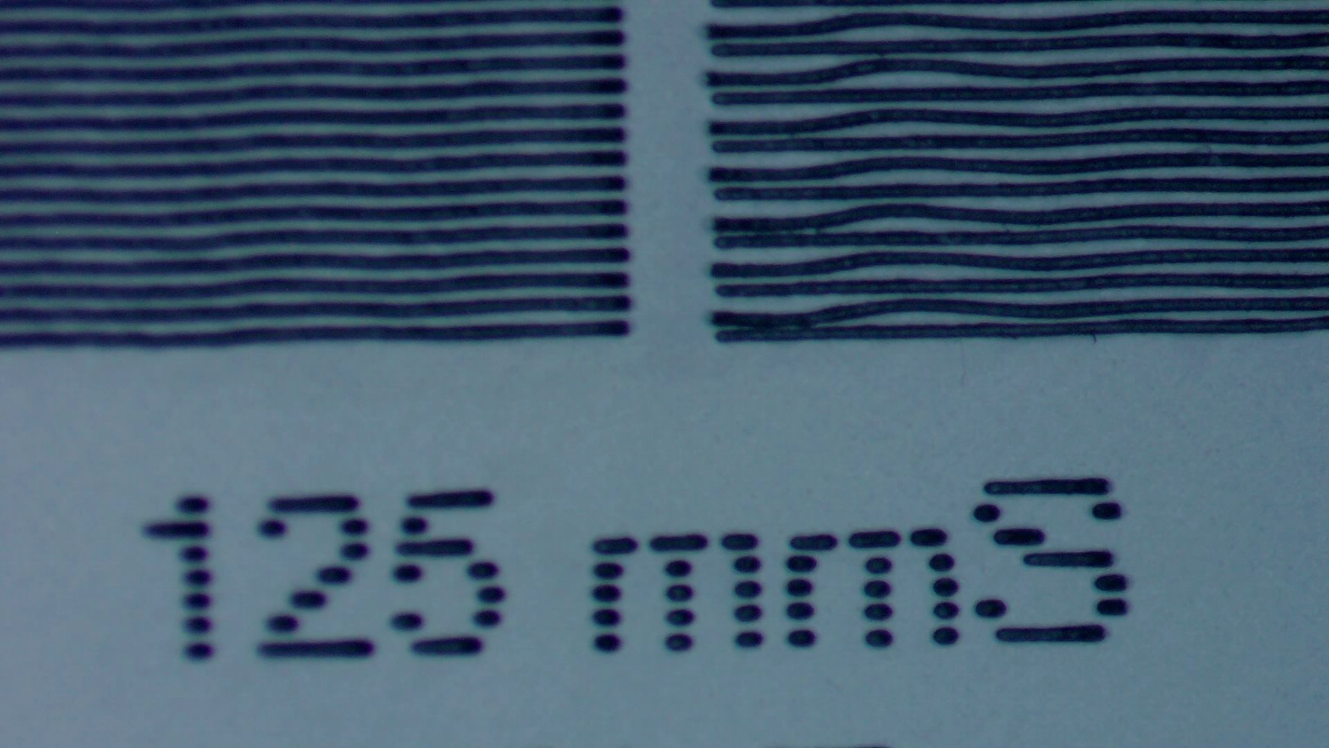
125mmS 100LPI 14/10% power.

60mmS 100LPI 12/10% power.
I am inclined to agree with the suggestion from ednisley that the may be a filter setting for the servo motors or something along those lines as there appears to be a resonance which is fixed regardless of speed. as can be seen in the 60mms engrave speed the wiggle is short and as we go up in speed the wiggle gets longer. so the so called wiggle is a constant time period as we go up in speed the wiggle gets stretched.
As shown in the previous photos the artifacts repeat more in the larger engraves.
Food for thought…
The Leadshine site does not have that driver (⸘‽), but it does have a CS1-D507S driver that is obviously different. If you have a link to the manual for your CL1-507-3LS, that will be helpful, as all my searches come up empty.
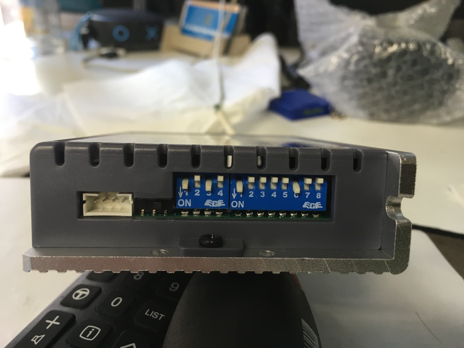
The switch settings on the CS1-D507S driver do not match what’s shown on the side of the CL1-507-3LS driver on the Thunder Laser site:

A photo of the data plate on the side of your driver (opposite the heatsink) will confirm that picture matches your driver.
Assuming your drivers match the CL1-507:
- SW1-4 = ON OFF ON OFF = 4000 step/rev
- SW5 = ON = rotate clockwise
- SW6 = OFF = enable auto tuning
- SW7 = OFF = Pulse/Dir
- SW8-9 = OFF OFF = default time constant
- SW10 = ON = 500 kHz BW
- SW11 = OFF = pendant
- SW12 = OFF = closed loop control mode
Assuming the CL1 functions are similar enough to the CS1, I can leap to some conclusions.
The CS1-D507S manual says nothing about auto tuning beyond the switch description, but it generally means the driver will adjust its internal settings to improve the step response. It is not clear what that would mean in this situation, but I’d turn it off (SW6 = ON) and see what happens to the 60 mm/s 100 LPI test.
Other than that, nothing sticks out.
Now, based on some doodling …
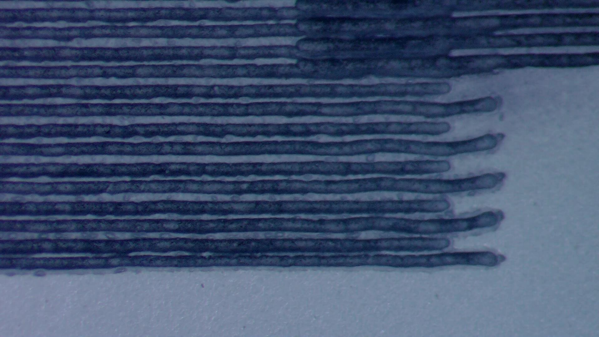
As you observe, slower scan speeds show a damped oscillation, rather than what looked like a relaxing offset at higher speeds. Running some numbers on the 60 mm/s 100 LPI scan suggests the oscillation has a period of 25 µs → 40 Hz.
Assuming your KH7050 machine looks like that, it’s essentially identical to mine, but with a box sticking out for the anode end of the 100 W = much longer tube.
Quite by coincidence, I recently ran a set of similar tests on my (simple stepper motor) machine and came up with a gantry oscillation with a 10 ms period → 100 Hz.
That’s Close Enough™ to the frequency of your machine to suggest my initial assumption of a slow servo loop filter was wrong. The initial speed of 500 mm/s you showed smears those oscillations across 8× the distance with the initial offset corresponding to the initial position error at the start of the line, which comes from the phase of the oscillation; the oscillation is so stretched we didn’t see the damped cycles.
Based on your series of tests, I think we’re seeing a simple mechanical oscillation of the entire gantry after a step change in Y axis position, rather than anything horribly wrong in the driver.
Bottom line: try disabling auto-tune (on both drivers) and see what happens. Most likely, it’ll look about the same, which will confirm that’s not the problem; whereupon re-enable it as before.
The RDC6442 manual has a section for Cutting Parameters containing an Idle Move Acceleration value with this comment:
idle stroke speed and idle stroke acceleration can be set higher to reduce the working time of the whole figure, but if they are set too high, it may cause the jarring of track, so comprehensive
consideration should be given to the setting.
There is a similar Y Axle Acceleration setting in the Scanning Parameters section, without any description. I think the Y axis values affect the speed / acceleration of the line-to-line motion.
Experimenting with those values will be instructive, as reducing the Scanning settings should move the whole gantry more gently from line to line. That’s the next part of my experiments here, so you’re sailing into uncharted waters on my map. ![]()
For the discerning DIY builder! ![]()
From the difficulty of finding even a link to the manual, a paper version might cost almost as much as the hardware.
1 Like
My searches didn’t result in much either only a datasheet for CL1-507 in Chinese.

here is a photo of the table on the driver - ignore the sticker as the X and Y drivers have been swapped.
I did try turning auto tune off without a noticeable difference to the low speed engrave.
I also tried adjusting the smoothing filter on the driver module with a interesting result from the default setting - what ever that may be.
set to 3mS didn’t appear to do much but when set to 12mS it threw out the scan offset way out
if nothing else just interesting to see the result of the smoothness filter.
Just because im completely out of ideas to test for the moment decided to tighten the X axis belt a bit but did not result in any visible change.
I suspect the wobble is from the Y axes, not the X.
The waving goes up and down, which would indicate issues with Y not X.
Just thought I’d mention it.
![]()
The doc always lags reality! ![]()
That’s unsurprising, as the offset comes from the timing mismatch between the laser tube’s output and the head’s physical position.
There being nothing like a good new problem to take one’s mind off one’s old problems (plus, I intended to do this anyway), I varied a few parameters that should affect the results.
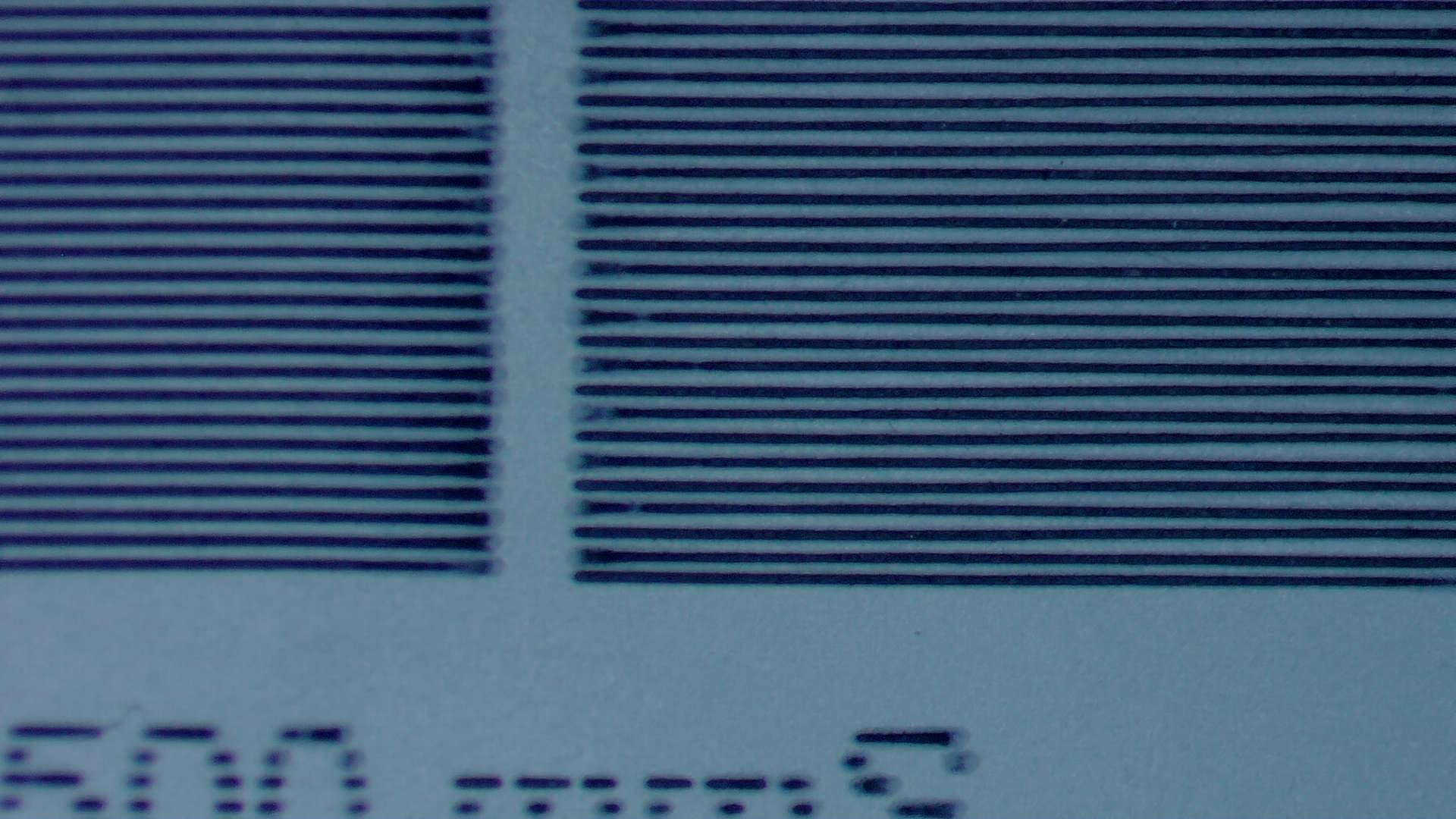
Today I Learned: the right-to-left return path (with the laser off) during uni-directional scanning spreads the Y axis motion over the entire length of the X axis scan:
![]()
Because the Y axis moves very slowly, the gantry doesn’t do any wobbulating and begins the next left-to-right scan (with the laser on) at the right place.
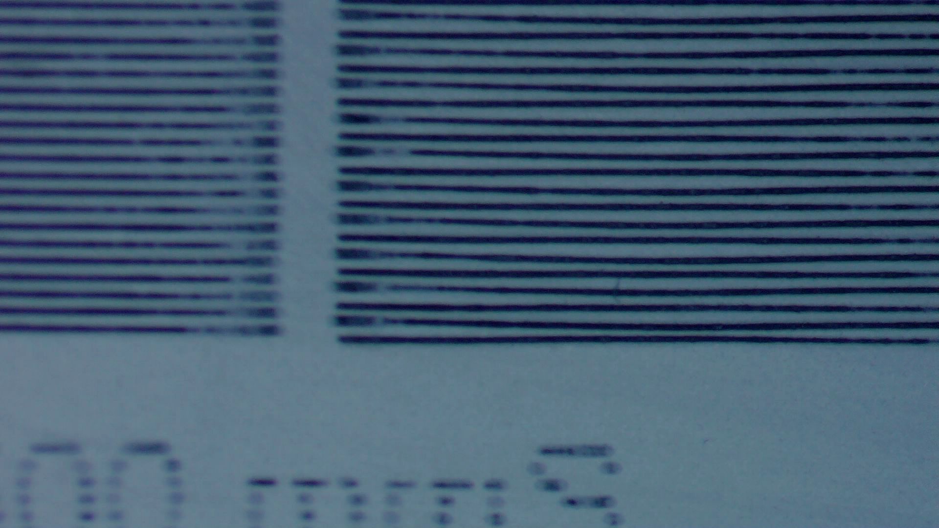
Bi-directional scan has a short move on the Y axis at the end of each scan line that shakes the gantry enough that it continues wobbling through the overscan region and well into the start of each scan line:

The original image is magnified by a factor of four.
The maximum error in the Y axis direction is 0.12 mm and damps out after 3 cycles. Each cycle covers 2.8 mm = 28 ms at 100 mm/s = 35 Hz. That’s a third of what I measured earlier while cutting test squares, so I’m not sure how much I trust either number, but it’s eerily close to to 40 Hz I came up with from your pictures.
The LightBurn Preview shows a 1.5 mm overscan distance and extrapolating the wobbulations leftward suggests the gantry starts the scan line with an overshoot from the Y axis motion. The cycle-to-cycle damping is about 50%, so the initial overshoot might be 0.25 mm.
That’s at:
- Layer speed: 100 mm/s
Line interval: 0.25 mmY acceleration: 2000 mm/s²Y start speed: 20 mm/s
I made five single-variable changes to the Engraving Parameters settings …
Line shift speed
- 500 mm/s
- 10 mm/s
Y Acceleration
- 200 mm/s²
Y start speed
- 30 mm/s
Today I Learned: The Y Start Speed (in mm/s) for engraving is capped by the Y Axis Jumpoff Speed (in mm/s², so perhaps the maximum change in speed), which is, in turn, capped at 80 mm/s.
Each of the five variations produced a result visually indistinguishable from the image you see above: the error magnitude and oscillation frequency are the same.
One possible reason: None of those settings have any effect, because LightBurn doesn’t do whatever the controller defines as Engraving. However, changing both the Y start speed and the Jumpoff speed should have made at least a little change to the results and did not.
Another possible reason: The 0.25 mm Y axis step is 20.8 motor steps (either 20 or 21 at 12 µm/step), so the fancy tweaks don’t actually have room to take effect, the motor thumps 20 steps, and the gantry shakes the same way each time.
Or something else is happening.
Soooo AFAICT the tiny wobbulations we are both seeing come from very very small flexing in the gantry hardware that can’t be cured by tweaking mechanical tensions or by twiddling config parameters.
I Guess changing any setting on the driver will upset the balance. As there is no feedback to the ruida controller. As the controller is trying to command something and then the driver is applying its own corrections.
Have been doing numerous test to try at least reduce the artifact.
I tried to tighten the Y axis belts on either side a little and making sure to adjust both side by equal amounts - this actually had a negative effect as i was now seeing the artifact on a 260LPI engrave on one side of the Uni Directional engrave whereas before Uni direction engraves were good.
So undone the tension on the side Y Belts.
I then tried to increase the tension on the belt from the Y motor to the coupling gear - the belt was already reasonably tight so adjusted a fraction more( now only around 3mm of deflection in total) when pinching the belt together (thats tight compared to what they show on you tube videos - so is it over tight and compensating for something else? )
Went through all the rollers on the X Y Axis’s again making sure not loose or too tight.
so after all that i think it might be usable (still waiting the hear what the correct X acceleration speed is from manufacturer - reduced from original setting)
Still pretty bad on low speed engraving but in the normal range it seems better and the artifacts may be reduced further with 2 passes.
500mm/s 16/10% power 100 LPI 20000mm/S^2

50mm/s 12/10% power 100 LPI 20000mm/S^2
So there appears to be a combination of things that contributed to this issue.
Aye!
You could try fiddling with the Scanning Offset Adjustment for various driver filter settings. The additional filtering doesn’t seem to move the ball toward the goal, so there may not be any point.
I think reducing the X acceleration enough to put at least the first two oscillation cycles in the overscan region would help, but the right value would also depend on the scanning speed. At 100 mm/s, two cycles are 56 ms long and the overscan is only 15-ish ms long, so the acceleration would be very low.
If, indeed, changing the X axis acceleration in the Engraving Parameters section has any effect, where no other change made any difference. ![]()
Good hunting … ![]()