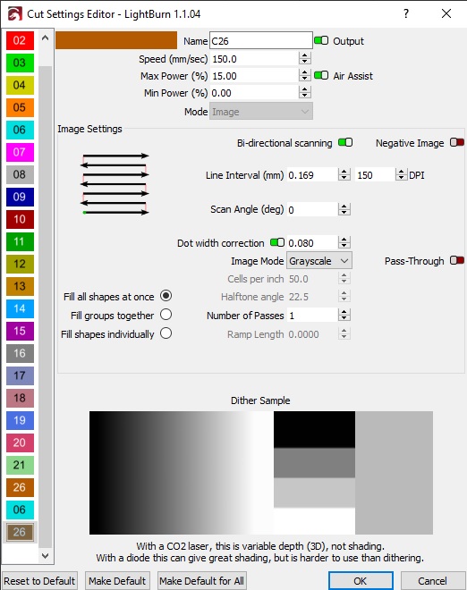
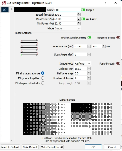
Can you show the design as well in LightBurn and the resulting burn?
Not certain but it may be due to your min/max range. Depending on the size of your CO2 tube the actual minimum addressable power may be around 10%. In that case, with your Max Power at 15% that gives you only 5% addressable range. I’m guessing that any grayscale that maps below 10% is either getting clipped off entirely (not burned) or if you have other settings on your controller that force a minimum power that it may be forcing all values below that threshold to the same higher value.
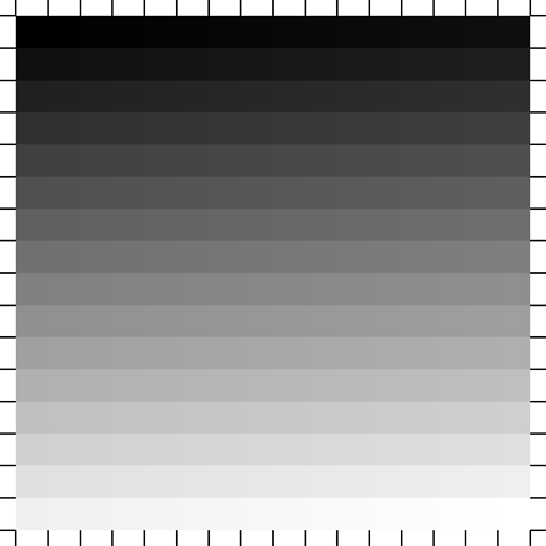
You could test this fairly easily if you run a test with a full gradient from 0-255. If you get nothing at the lower levels then it’s getting clipped. If you consistent burning at the lower ranges and then a gradual increase then you likely have some other setting (on the controller) that’s forcing a higher minimum than 0%.

the one that looks like theres differences was done in dither
The test pattern at lower right, is that dither or grayscale? If grayscale, was that showing 0% gray to 255%?
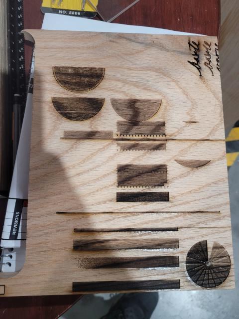
at the lower right it was vector lines done in different layers not a bitmap image I just used that to find my range in the material
I suggest you run a test pattern that runs a full range of grayscale. This should reveal the clipping or min-value behavior and at what ranges it occurs. That will tell you where to look next.
this is what i ran where you see the solid dark squares i ran this at varying max/min power settings and still got solid squares it only seemed to make differences where there was white and black
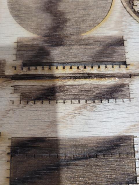
when I put the min at 0 I actually get to see the black lines appear but no matter my max or min power value it seems to just fire at the selected max value with no variation
Ah… nice. Didn’t know what the squares were supposed to be.
Have you tried this test in LaserCad?
yes it works in laser cad
leads to believe there is an issue in lightburn
Interesting. So likely not a machine setting unless you’ve changed things between using LaserCad and LightBurn.
We’ll need someone else who’s done this with a Trocen controller or one of the LightBurn folks to provide some insight.
Nothing changed between my settings as far as I know, its the same settings, I mean for now I can at least get it to work through lasercad I’d love to have this fixed since i have another 150w CO2 that i run the same files on flawlessly
Could you try saving the ud5 file from LightBurn and running it in LaserCad? That will tell you if it’s something with the ud5 generation.

Is that other machine also a Trocen controller?
You’re not using Grayscale, which is the specific setting the original poster was trying to use and having issues with. It’s possible that grayscale is not working on Trocen, but I’ll need to check.
In order to use grayscale he will need to use a vector not a bitmap inside lightburn. Most trocen controllers do not see Lightburns response to a bitmap sent using grayscale
