Boss Laser LS-1416 with china barrel rotary

New here to the forum.

I’ve spent hours on this and cannot figure it out. So I’ve come looking for assistance.
One issue is the conflicting data I have found out there…
I have read as many posts as I can find and manuals on lots of laser rotary attachments.
I must be missing some key knowledge about how the software works etc.

I have a Boss Laser LS-1416. The y-axis driver is a MD442:
http://www.leadshine.com/UploadFile/Down/DM442m.pdf

The switches are as follows:
1: on
2: off
3: on
4: off
5: on
6: on
7: off
8: on

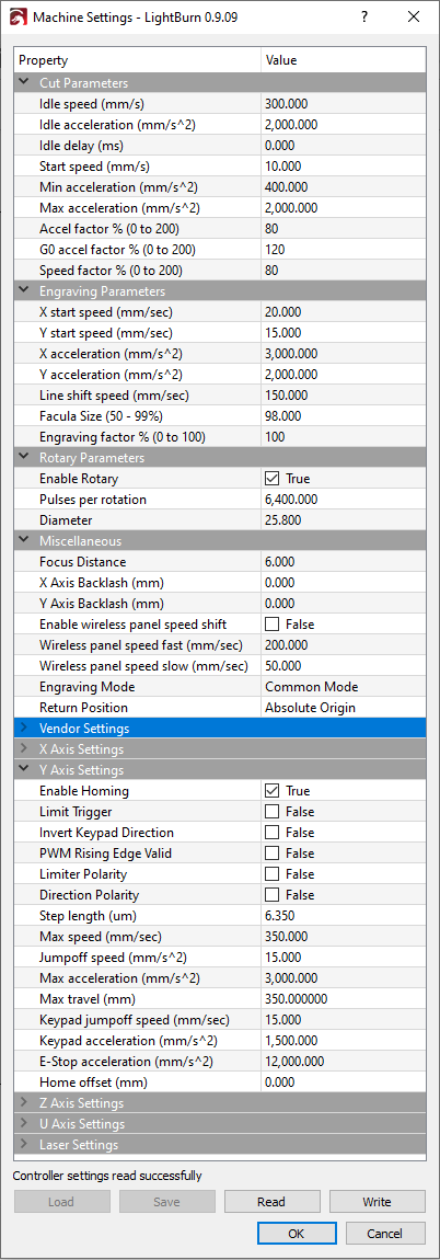
From the DM442 manual this means the steps/rev is 3200.

The motor on my roller says the following:
STEPPING MOTOR
TYPE 17HA801Y-22P1
FH190809 Smooth

I am assuming it is a 200 step motor, 1.8 deg/step.

The drive pulley and driven pulley are identical, so the gearing is 1:1.
This is the ebay listing I bought the roller from:

It did not come with an aviation plug so I bought one on amazon and soldered the leads appropriately.
I did not like the knurl of the rollers so I sleeved them with 1" shrink wrap.
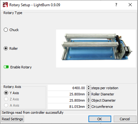
Afterwards their effective diameter is 25.8mm.

When I read how to use the rotary attachment specifically marketed for the Boss Laser, it states to set the cirlce pulse to 4250 and the diameter to 35mm, no matter the size of the object I’m engraving.
4250 does not equal 3200. This is where I started to have some confusion.

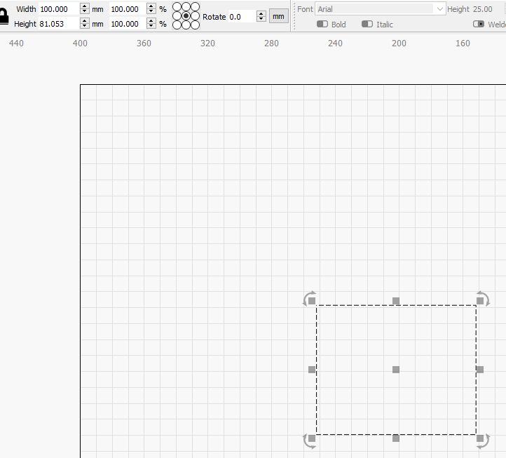
To experiment, in RDWorks I wrote to the laser a circle pulse of 10000, and a diameter of 5. I then framed a scan file with size 20X81mm on the laser. 81mm is the circumference of the 25.8mm roller. The rollers rolled for a long time. I changed the circle pulse to 5000 and they rotated less, still many full rotations. I grew confused and set the circle pulse to 3200, what I believe the stepper drive itself is set to. I ignored the 4250 in the boss laser rotary attachment manual for now. Eventually, after trial and error, I got the barrels to rotate what looks to be 360 degrees with the 20x81mm scan frame. The diameter setting i wrote to the laser from RDWorks was 12.9mm, exactly half the diameter of the roller itself…

What is going on here? Why would the boss laser manual say to set the circle pulse at 4250 while the driver is set to 3200? For their rotary chuck attachment, which is what actually drives their roller attachment, they say to set the pulse circle to 10000!

I’d really like to fully understand the math and theory behind it so I can etch pieces of any diameter confidently. A big thing for me is having the image come out with the correct aspect ratio. I also am planning to do some scans where the ends of the scan connect so you cannot detect the start/end of the wrapped image.

I hope for some quality replies so those in the future with this issue can really understand whats going on.

Thanks!

This is the boss laser rotary attachment manual. As a new user I can only put 2 links in my original post.

https://www.thunderlaser.com/uncategorized/rotary-axis-attachment-has-a-wrong-cylindrical-engraving-cutting-size.html

I do not have those settings available in the rdworks software and the shown text is not available in the soft file…

I used RDworks prior to getting LB, and messed around with this myself. There are 2 things going on here, # of steps/revolution, and # of steps/distance, which are not the same thing.

The first thing you need to do is get the rollers moving the correct distance. I am assuming you know to Read the settings from the controller, and then Write the new settings.

Using the numbers that you provided:

  1. set the diameter in the settings to the same diameter of the rollers (25.8mm)
  2. frame your 81mm rectangle, and adjust Circle Pulse until you get exactly 1 rotation of
    the roller.
  3. once you get 1 rotation dialed in, adjust your rectangle to be 162mm, download, and frame it again
  4. the rollers should go around exactly twice.
  5. if this all works, you are done with the Circle Pulse, and diameter settings.

On a roller type rotary, the distance the roller travels is the same distance that the surface of your item rotates, so you won’t be changing the diameter. When a rotary chuck is used, you need to enter the diameter so the software can calculate the distance travelled, as it only knows how many pulses/rotation.

Hopefully that clears things up for you.

Kevin

Ok thank you Kevin.

I installed LB and set the rotary to 3200 steps/rev, the diameter of the roller to 25.8mm, and the diameter of the part to 25.8mm. I framed an etched rectangle 2X81.053mm.

I get half a rotation. I set to 3200 steps/rev because thats what the drivers set to in the machine. Is this not the correct thing to do?

If i up the steps/rev to 6400, OR drop the diameter to 12.9mm, i get what seems to be a full rotation.

What is bothering me is it doesnt make sense, yes it works if I set the steps/rev to 6400 (double the driver output), and the roller diameter to what it is, but I dont understand why it works. Maybe my stepper is a 400step/rev motor and not 200 step/rev?

I cant get the specs out of the chinese mfg on ebay. they do not reply. and there are no specs on this motor ive been able to find online. I dont want to have it work and not understand why. I realllyyyyy want to understand why it works so i can tweak it precisely if need be.

I cant find anywhere on the motor a designation for steps/rev or angle/step. i may have to dismount it and look on the mounting face?

Double check the dip switch settings, and click them on and off to make sure they are fully one way or the other. (specifically switch #5, as that is the one that switches between 3200 and 6400). You want the steps higher anyway for better resolution.

99% of the motors are 200/rev.

i flipped the SW5 to off so it should output 6400 steps/rev now.

now with 6400 step/rev and the roller diameter as is it only rolls have the distance of the outputted file height dimension.
if i set the objet D to 25.8, roller D to 25.8 and the rectangle is 2x81.053 it turns half a turn.

When the normal y-axis motor is plugged in it worked fine at 3200 steps/rev. will it not work correctly now that i changed the dip SW5 to off?

the stepper on the y-axis is a CW-MOTOR 42BYGH192-47 CW NO: 19.07.27

great it seems their website doesnt work…

own an expensive boss and have the cheapest rotation axis ?!
buy a chuck with 3 jaws, then you can always go according to the diameter of the object to be engraved

Changing the dip switch to 6400 will affect your y axis, so this is not the best solution. They should be set to whatever worked for the Y-axis.

You should be able to adjust everything in software. Can you upload a screen shot of the settings?

agreed, it is a rebranded chinese laser, but the tube and optics are supposedly upgraded.

I plugged the normal y-axis back in and it travels only half its prescribed distance


when you say cheapest rotation axis do you mean the poorest resolution steppers?

Im wondering if i could upgrade them to something with higher resolution and flip the DIPs accordingly.
I’m rather new at this and it is a brand new machine.

So you are saying with the driver dip switches back at 3200, and pulses/rot at 3200, your image is only half?

correct. that is why im confused to begin with, and suspect a 400 step/rev motor

cheap in the sense that it is poorly constructed
2 rolls only work on things that have the same diameter at both ends, glasses that are narrower at the bottom and wider at the top do not work on it, since the rolling circumference is not the same
the motor is okay with its 200 steps

ah ok i understand what you meant. the reason i purchased it is i want to etch many of the same object at a time. the objects are about 2cm tall and 2cm in diameter. cylinders

A 200 step/rev motor that is micro-stepped at 3200 will have more than enough resolution.

So what happens when you set circle pulse to 4250 and dia of 35mm?

You showed a screen shot of machine settings. Can you show a screenshot of the “Rotary Setup” at the bottom under “Tools”?

i plan to keep the dip switch at 3200. i guess i will just have to keep the step/rev at 6400 in the software to achieve full rotation.

When i change it to 4250 and D=35mm it does not complete even a half rotation, almost, but not quite there.

Aha! I can still edit my posts!

as a new user i can only post 5 times per day:

when i input 6400 steps/erv and 25.8mm as the D in the machine settings and then view the rotary setup it has rotary-type selected as roller. rotary axis is Y, steps per rotation is 6400, roller diameter is 25.8mm, object diameter is 25.8mm, circumference is 81.053mm

I was able to have my max post count and image upload increased. I’ll post the messages i had between Kevin and I below for future people looking and those interested. A solution was kind of found but I’m still confused about the math behind it and why it actually works.

image

Kevin:
I think the problem is because of the diameter of the timing pulley looks to be approximately half of what the diameter of the roller is. The motor is direct drive to the roller, so even though the # of rotations is 1:1, the distance traveled is not.

Me:
hmmm, that is interesting. so if i set it to 3200 steps/rev and the D to the effective diameter of the belt sprocket it may work… IIRC i measured the sprocket diameter as 11 or 13 mm, somewherer in there. half of 25.8 is 12.9 so you may be onto something.

Kevin:
You will be more accurate using the diameter of the roller to dial it in than the pulley.

I would use a large diameter cylinder, play with the steps/rot until it is perfect, and then work the math backwards to get the steps/rot for the diameter of the roller. Easier measuring large measurements than small.

Me:
Agreed with thanks for the confirmation of the idea. im about to engrave a plastic bottom 125mm in diameter. what should I set the line interval to? would it be something like circumference divided by steps/rev? so 390/6400=0.061?

Kevin:
I use 0.06 mm for most of my rotary. You can also de-focus a bit, which allows the beam to be wider, and overlap the previous scan. You gain speed but lose a bit of resolution, or you may notice a jagged edge if set too course.

Me:
OK,
I found with the large bottle a step count of 7100 and diameter of 25.8 is just about perfect. at least on the framing of it. im going to run it now to see what it really comes out like.
thank you for your help, will report back soon.

Ok it is running. But the oddest thing happened at the beginning. I have a tall skinny rectangle that’ll wrap around the whole bottle. I set the origin at the top right so when i run the frame command it doesnt roll really fast to the bottom right/left of the rectangle and start from there. However when I started the actual cut it did just that! instead of starting from the top right like i wanted it to it rolled to the bottom of the image file and started. anyway to change this? the start location or roll speed to get to starting point of etch? the roll speed to get to the starting point was fast and im concerned about slippage.

The test came out good on the bottle. the etch came right up to the start, there was minimal gapage.

I’m not quite sure how to backwards calculate the real step count and diameter of roller so I may just leave it as it is. Maybe (25.8mm / 7100step/rev)*3200? that equals 11.62mm, so the effective diameter of the belt pulley may be that. very weird.

Thank you all for your help today. I’m sure I will have questions in the future and I’m glad this forum exists.

thank you again for all your help!