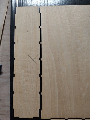
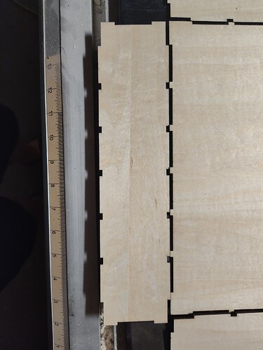
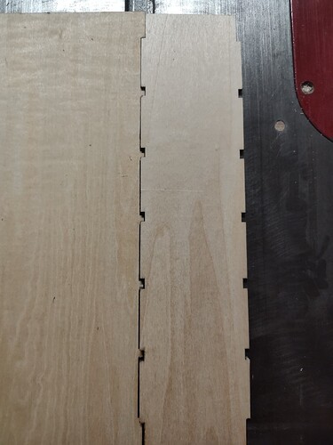
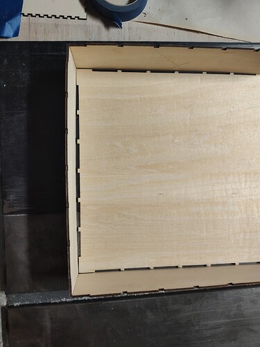
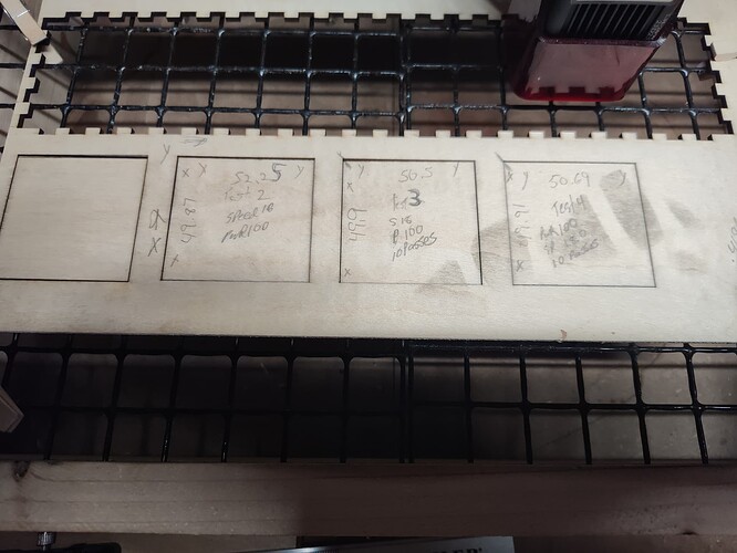
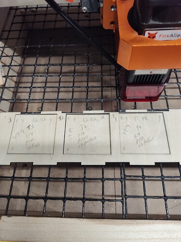
I have been fighting Boxes.py, and lightburn for the past week or so trying to build a sliding drawer box. The issue I’m having is in lightburn? all the joints line up and look to have a good fit on the screen. however when sending the job to the laser,( via onedrive to the shop pc) most of the tabs do not line up after cutting them out. the back panel tends to be longer by 3/8" as shown in the photos, which means even if the tabs lined up properly, the top and bottom will be to small.
Ive done 2 versions of the same box only changing the number of fingers, and still having the same result.
I cannot determine where the error is.
I’m using latest version of Lightburn,on both my computers, and Masutar pro by Fox Alien. I need some help please.
Thank you
Ray
There are a couple of possible root issues:
- The design itself is not properly sized. You indicate that you’ve checked this so likely not the issue. Please upload the .lbrn file if you’d like a review.
- The laser is not cutting dimensionally accurate to the design. This seems the more likely issue.
Can you confirm that your laser cuts dimensionally accurate parts? If you cut out a 100x100 mm square, do actual measurements correlate those dimensions?
In your example where the parts don’t align, is it possible that the tabs on one part were cut along the X-axis while the slots on the other part were cut along the Y-axis or vice versa? If so, that would support the hypothesis.
I’d suggesting running some tests to confirm dimensional accuracy.
What is your kerf setting in Lightburn?
279 paint drawer original.lbrn2 (69.8 KB)
Thanks for the reply,
I went and tried another box generator to see if I came up with the same result. Sadly, it is the same result. After further review, the offending piece is the back piece in this file. Length is cut on the (Y) axis to maintain grain orientation.
The test pieces were cut @50mm so the error will be multiplied by 2 in order to determine the error across the (Y) Axis of 100 mm. God knows I have $40. worth of scrap to use.
test 2) 52.252= 104.5 difference of 4.5 mm
test 3) 50.52= 101.0 1.0 mm
test 4) 50.69*2=101.38 1.38mm
so the error across a piece measuring 279.4mm will be an issue
The (X) axis is within tolerance.
I may change the (Y) axis belt for GP. but tension is good, and no stretching noted. especially since the largest error is towards the left side of the (Y)axis.
I am completely lost in this issue. The size of this box only multiplies the error.
So it’s either in my settings, or in the machine itself.
I hope this makes things simpler, to understand the frustration of the loss of money and materials.
Thanks again
Ray
Hey Ralph
The kirf is not the issue, but in lightburn it’s set to 0, However when generated from boxes.py it’s set to 0.63 for a nice friction fit. I’ve had some success with smaller boxes at this setting. I think it’s the actual overall size of the box thats causing the issues I’m having across the (Y) axis
Thanks
Ray
Correction, .063 is the setting used. not .63
Check the stepper motor settings in GRBL. Let’s see if there’s anything unusual there. Run this command in Console and return the full output here please.
$$
If that doesn’t yield anything obvious you can go through a stepper calibration on the Y-axis to adjust.
However, I’m a bit concerned that your tests are not resulting in consistent measurements. A 3 mm variance is quite significant across 100 mm.
Can you check to see that your machine is square? Do the left and right sides of the the gantry touch touch the front and backs of the machine at the same time? If not, sort out what’s causing the out of square and resolve it.
Also, make sure that you don’t have a loose stepper pulley which is slipping on the stepper shaft. That could account for some measurment issues but your symptoms don’t match this scenario well.
Here is the $$ settings as of now from Lightburn. Imma attach the settings from laser grbl to follow.
Stream completed in 0:00
$$
$0=10
$1=255
$2=0
$3=0
$4=0
$5=0
$6=0
$10=115
$11=0.010
$12=0.002
$13=0
$20=0
$21=1
$22=1
$23=3
$24=25.000
$25=8000.000
$26=250
$27=3.000
$30=60000
$31=0
$32=1
$100=80.000
$101=80.000
$102=1600.000
$110=4000.000
$111=4000.000
$112=500.000
$120=300.000
$121=400.000
$122=400.000
$130=380.000
$131=380.000
$132=50.000
ok
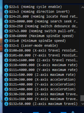
From laser grbl V7.11.0
All looks ok, but I’m still fairly new too all these settings.
These are steps/mm for X and Y respectively and look fairly typical. Are you aware of any hardware modification on the machine itself post delivery from factory?
I’m still a bit worried about the seemingly inconsistent dimensions in your test but 'd suggest running a test for a very tall rectangle, as-in nearly the full height of your bed, and then using that as input to the axis calibration tool in Edit->Machine Settings->Calibrate Axis. That should fairly quickly rule-out a calibration issue.
retested after tightening belt, readings are more consistant, however still out of tolerance for a project this large. So I;m thinking I need to change the belt on the Y axis and and hope it’s corrected but I’m not certain that will solve the issue.
readings are as follows.
T1) 52.82
T2)52.82
T3)51.88
average over tolerance =52.5
All across the (Y) axis.
I don’t know where to go from here.
Thanks for all the help folks.
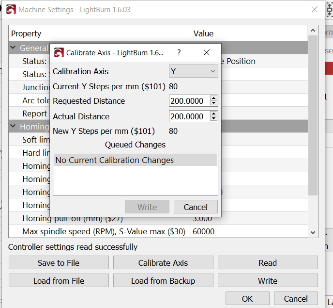
The calibration doesn’t show any changes, or a way to have the machine calibrate. Am I missing something here???
In the field Actual Distance, you indicate the measured value of the output for the indicated input Requested Distance. In other words, if the input design was 200 mm, what was the actual output size? Once those values are different you’ll have the opportunity to Write the changes back to the controller.
So If I run the project again, Prior to starting? I should come back to the calibration page too see if the requested distance matches the actual project distance across the Y Axis? If it doesn’t then change the value in the calibration field then run the Job?
Would I have to make any changes in the laser Grbl also?
I can’t shake the feeling that there is a conflict somewhere.
Since the $$ settings look normal, the swappage between the roller set up and now isn’t an issue. Is that fair to assume. I have had this machine in all intended modes. Which maybe why I’m thinking there is a conflict in the software?
Make a design explicitly for testing. A long rectangle along the Y-axis. The larger the shape the less prone to measurement error.
The calibration pages allows you to calculate and implement the necessary changes to account for the difference between the planned design dimension and the resulting actual dimension. LightBurn will use the input values to calculate a new steps/mm value which is then written to the controller.
GRBL settings reside on the laser controller and are shared by all accessing applications. Changing in LightBurn will make those settings changes available in LaserGRBL and vice versa.
I’m not following the question. Are you asking about impacts to rotary function? If so, assuming that the rotary function relies on Y-axis then this calibration will have an impact on the rotary. In that case, simply revert the steps/mm setting or manually set the value by issuing this statement in Console:
$101=80
Before doing so, retain the newly calibrated setting so that you can easily revert to that after you are doing using rotary.
Thanks,
I did as you suggested, I made a test burn @279.4 sq. Ran it, (x, 279.9,)(Y,291.5) Thats a 12mm overage. So If I understand what your saying about the calibration, I would enter the value of 267 to compensate for the overage? Or do I subtract that number from the actual project,and realign everything, then pray it comes out right?
I would literally have to start from scratch again, because it just dawned on me that, if the small wall pieces are out? so will the top and bottom pieces,which may be another factor. However the sides were also cut on the Y axis and they seem to fit fine in the finger joints. only the back wall piece is coming out of wack.
Ray
No.
In the Requested Distance field you would enter 279.4. Then in the Actual Distance you would enter 291.5. Then LightBurn will calculate and populate $101 to account for the difference. If you then run a test again the actual burned size should match the designed/requested size.
If what you’re dealing with is indeed a general calibration issue then all parts would be affected in the same way. Depending on the orientation of the parts in the design it may still be close enough to fit but that will depend on the specific design.
ok, So I will try this method without full cutting them out, and double check the measurements. before committing.
Thanks for all your help. I truly appreciate it.
I’ll get back in tough either way. Hopefully with a successful project.
I am responding with no joy. After attempting multiple tests The output of the laser is different than what’s requested. there is no consistency, I have checked the physical machine for loose fitting parts or excessive play, double checked belt tension, all is good.
I played around with the calibration settings, nothing changes.
Nothing has worked right since the updates. I think I have to uninstall the machine and start from scratch yet again.
This implies that something didn’t go right. There’s no scenario where a change to the steps/mm setting ($101) would not have had a direct impact on the output.
Try confirming that a change was indeed made. Run this to extract the latest GRBL configuration and please return the output:
$$
