4.75 box proto_backup.lbrn2 (48.9 KB)
The laser was not cutting this poster board at 80000 SValue/$ 30, so I went back to the GBRL3M and laser started cutting, as it should.
The older version of the file was for 3mm stock, since the poster board is 4.75mm thick, I started a new prototype to test. Once I can get a box built out of the cheaper material, I will attempt the 3mm intended materials after updating the file from Boxes.py
the Kerf is determined by the test options in Boxes.py the best fit for my laser is 0.063 with 3mm stock. Fox Alien 20W Laser with air assist.
Increasing the value has no bearing on power. The only relevant component is that the value match.
It’s possible that cutting characteristics could differ slightly between GRBL and GRBL-M3 due to implementation of variable power in corners but that implies a more fundamental issue with the cut settings. You should have had normal cutting behavior on straight sections.
Your axes were not calibrated when you were determining the kerf setting. You may need to revisit that, especially if you were pairing cuts made along X vs Y axes.
You may need to revisit your kerf values post calibration.
Make sure, however, that the cut dimensions are close to the nominal dimensions in your design. Just in case there’s something more going on.
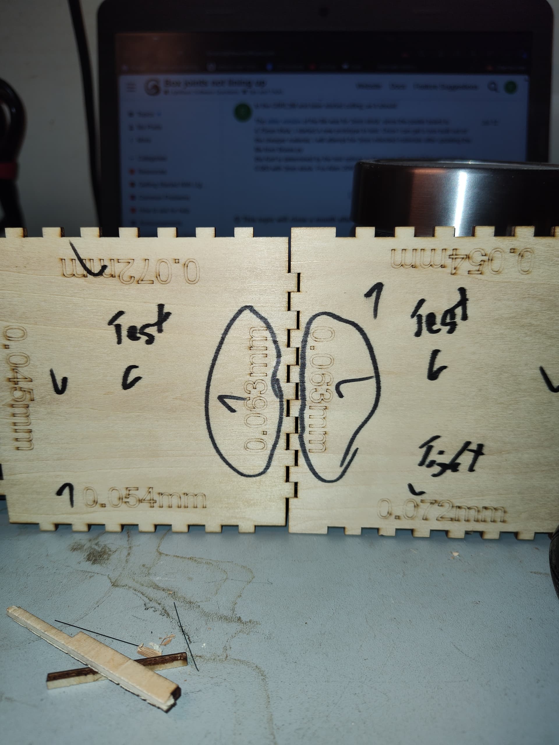
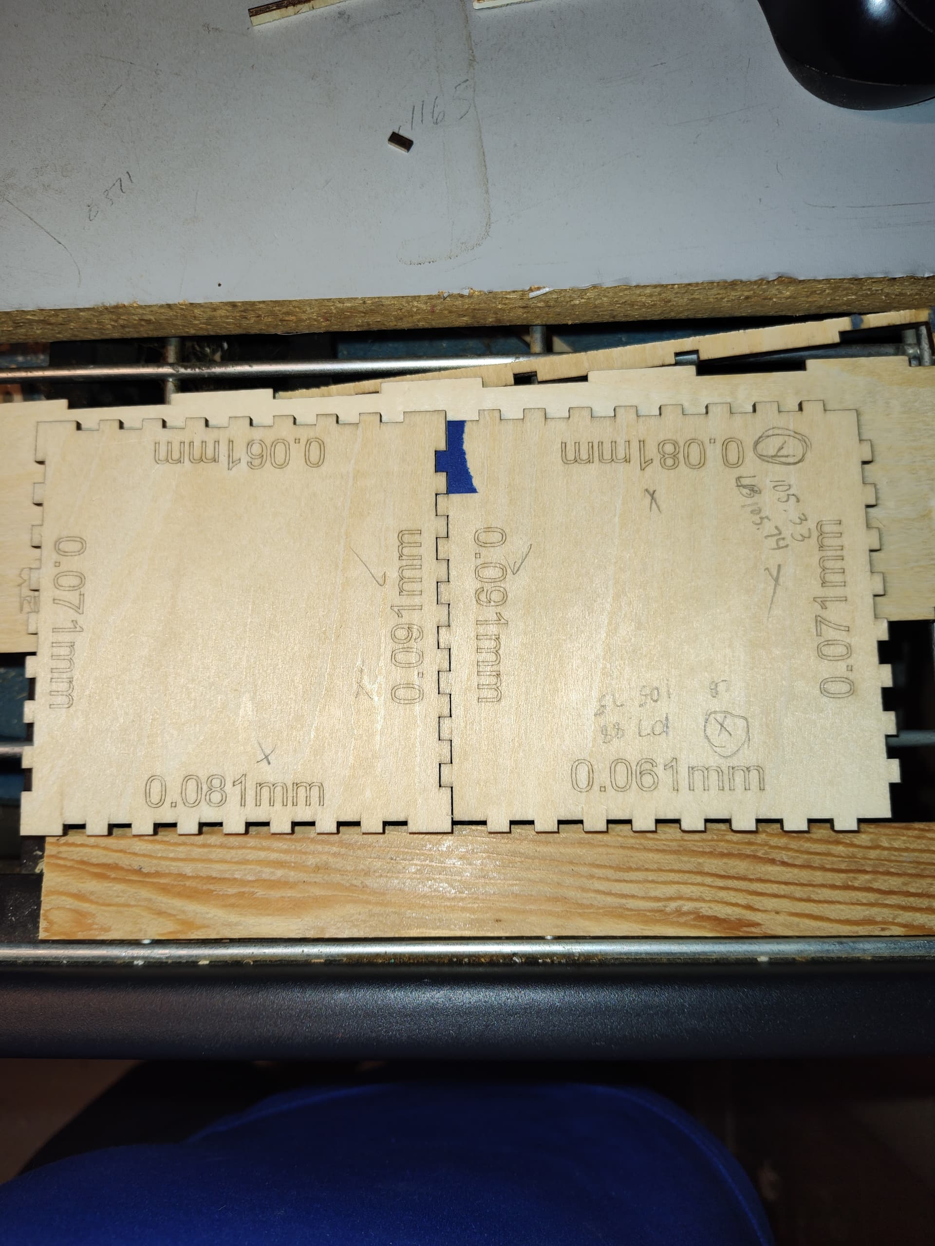
(upload://sZNaNvc96GW7tjwtuJrwBvdRqrY.jpeg)
Cut test is done, in the fitting, the only joints that work well are the joints on the Y Axis. The X axis joint are still not lining up correctly to get a good test fit.
So I f were to go and rotate the parts 90 degrees, to cut on the Y those would be ok, however top and bottom still have to mount to the sides and back and have to be cut on the X, I think further calibration is needed
If it’s that the cuts don’t line up, then yes it’s probably still a calibration issue. If it’s more of a kerf issue then something that hasn’t been mentioned is that on a diode laser, your beam is rectangular or oval shaped, not round. Which means that your kerf will be different on the different axes. This video does a good job explaining that situation.
I have seen this video, I’m aware that the beam is rectangular, it’s still the alignment of the fingers not the kurf. The fingers need to meet to correct for kurf to be corrected, to tight will require a little sanding, but if their not lining up then, the laser is cutting the path incorrectly. I cannot have misaligned parts, the box will not go together.
I do think you need a more accurate measuring device than a steel rule to figure out the settings with math, therefore I believe trial and error is the method you need to use for calibration from this point. It looks like you are close. Make a guess as to how much it’s off and change the setting for that axis. Run a test cut and see if you went too far or not enough and readjust.
for the last burn test for the kurf? measurements were done with the digital calipers, steel rule was just quick reference.
just so I’m clear, should I just run a series of 100mm lines, measure add or subtract the difference from the $100 measurement you had me input yesturday?
got a box to work with now, thanks for all the help. I just have to figure out how to get all the fingers in the right alignment and at the 3mm material I plan to use.
I will spend more time on the X getting it calibrated before going into the other material. I’ll let yall know the outcome if interested.
I’m not the one that gave you the formula or numbers to input. What those numbers represent is the number of steps your stepper motor must undergo to move the laser 1mm. Looking at past posts it looks like your x axis is set at 76.679, so for a 100mm line your stepper motor is moving 7667.9 steps.
To calculate the new setting for Steps/mm = (Current Steps/mm) x (Commanded Travel) / Actual Reading. In this situation 7667.9/actual length of line.
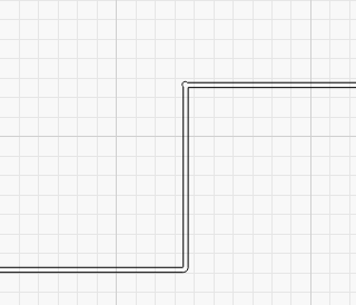
I’m taking a closer look at latest design file that you uploaded. The part labeled “out box wall” seems to made up of two outside perimeter shapes. Is this intentional? If so, what’s the purpose of this.
It’s possible that this is skewing your results. If you’re continuing to have issues I’d suggest eliminating any sort of kerf compensation altogether and working with nominally dimensioned pieces made specifically to test the results. Make sure that parts align and fit.
Only after that introduce kerf to the conversation.
Can someone please check my calculatiions?
76.679 x .98= 75.145
(76.679/100) x (100/102)
.76679x.98= .75145= 75.145
I would input this into $100 for the X axis and see if the correction is on point?
Not sure what your actual output measured as you have 98 & 102 in your equations, but you have the formula backwards.
If your output was 98mm when 100 was requested the formula is
(current steps x desired travel)=
76.679 x 100 =7667.9
(result of above equation / actual results)
7667.9 / 98 = 78.244
If your output was 102 when 100 requested
7667.9 / 102 = 75.175
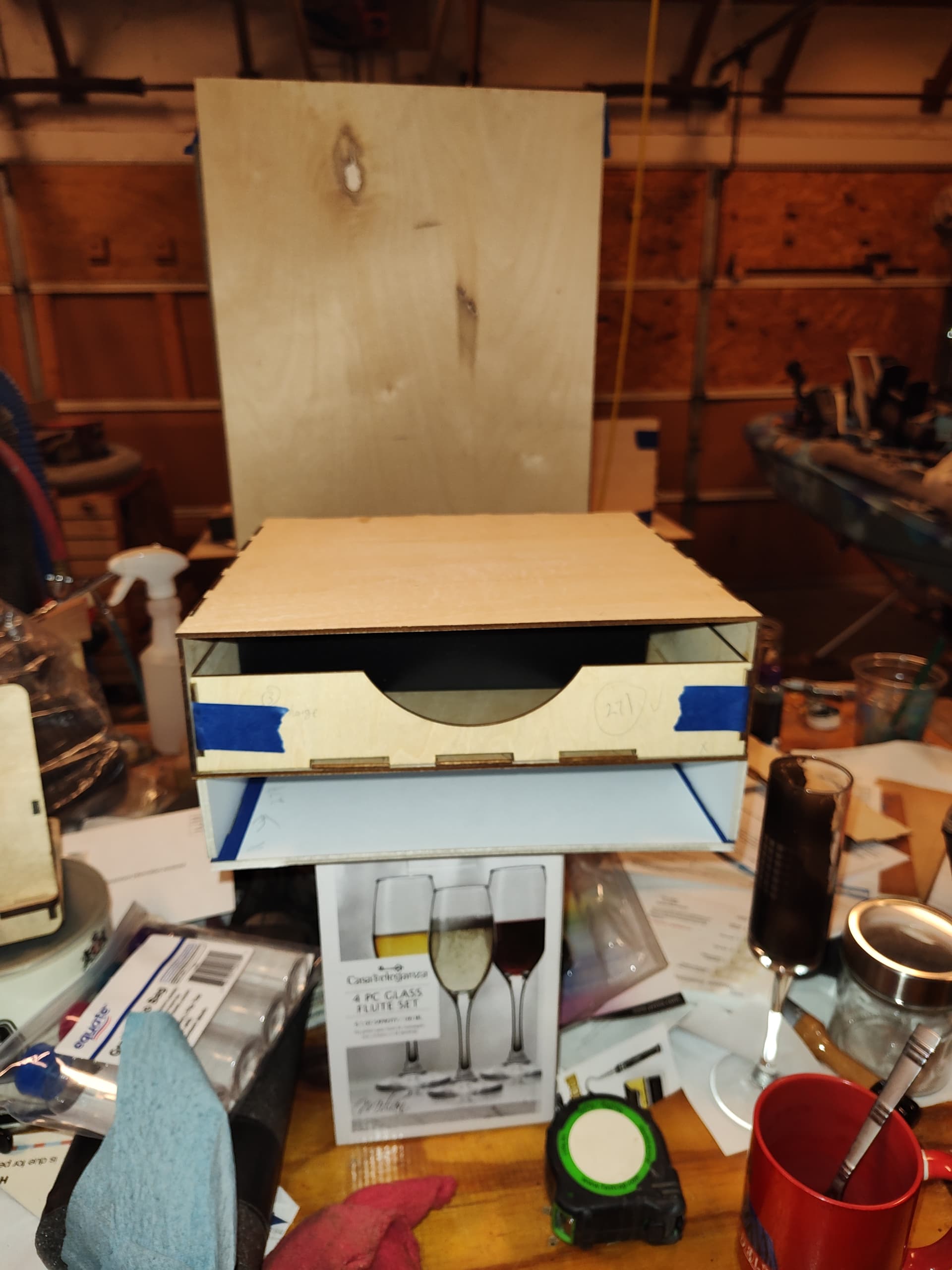
thank you again for checking me, and for all the help. here are a few photos of the prototype finally finished. Even though I’ve got a product, the fingers continue to be misaligned. The aggravating thing is it’s random. Is this typical? Changing the belt has helped a great deal, however I’m still getting inconsistencies. Can you think of anything else that needs to be checked?
I’m going to try another one from the default file, to try to pinpoint these inconsistencies.
Also, if I were to duplicate each piece 4 times, and assign each side a different layer, would that speed up the cutting process? instead of the laser going in circles on one path?
Ray
When you run the same job and get randomly different results, it’s a mechanical problem.
It looks like you’ve eliminated quite a few mechanical problems and corrected several mis-calibrations, but there remains (at least) one more mechanical problem.
The hardest part of debugging, at least for me, is when I’ve checked something and decided it’s OK, but overlooked a detail. At that point, I know the problem must lie elsewhere, so I’ll look everywhere else for the longest time.
Now that you’ve eliminated the obvious problems, start from the beginning and examine everything again. Other folks have discovered how subtle the problem may be: