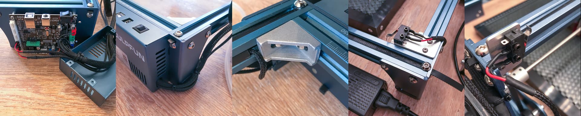
on my sculpfun s9 grbl 1.1h runs with the option homing_force_set_origin when compiling. home position is selected as on my routers rear right and there are also mounted the limit switches.
with grbl-controller/candle everything works fine. but as soon as i use lightburn it doesn’t work. the homing works but with the jog-function it only works if i set ‘front left’ as home position under the device settings. with the correct setting ‘rear right’ both x- and y-axis are moving the wrong way around when jogging.
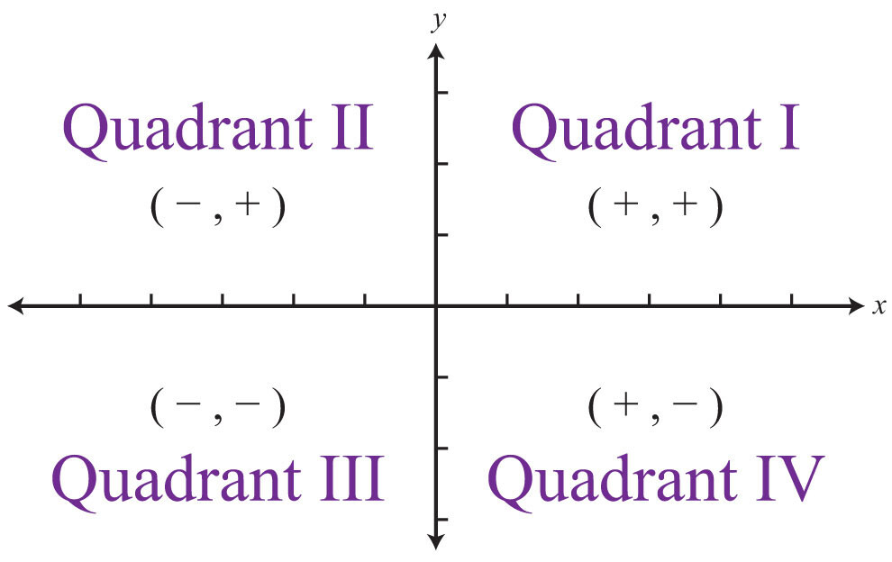
I can’t speak to Candle or LaserGRBL. I can tell you that LightBurn only works properly in a positive coordinate system. So if origin is at top right. Numbers will be positive going left and down.
I want to say that LaserGRBL may always assume quadrant I although not sure how offsets are handled in that case. Or perhaps it’s just a matter of changing the button configuration in LaserGRBL but not sure. A quick look reveals that LaserGRBL uses G53 in its jogging commands. You can compare this to LightBurn by enabling “Show All” in LightBurn Console and then jogging.
what i wonder is that after homing the displayed values for x and y do not reset to 0 - i have to click on ‘get position’ and then it says ‘0 0’. is that the normal behaviour in lightburn? candle and lasergrbl autoset the displayed machine-values to 0 after homing?
weren’t this a shame when a paid software couldn’t work in negative workspace like most professional equipment and also both before mentioned freeware?
I don’t think this is relevant as long at the position after “get position” shows 0,0. You can also check this by issuing ? in Console.
Neither candle or laserGRBL directly affect the machine origin values. That is tracked by the controller. Any software can query either machine position values or work position values.
I suggest you try the software and decide if the software and the model have merit. There are certainly benefits to how the software works. Being in compliance with all major laser programs including those for more industrial machines I think is a positive rather than conforming to CNC style traditions.
It occurred to me that you may not be aware of an alternative. You could set a work offset to position 0,0 at bottom left and set origin accordingly. This could potentially allow you to work in a consistent way across programs.
of course candle and lasergrbl do not affect/mess around with the machine values. but they show at the end of homing the correct machine position where lightburn needs obsolete manual interaction.
in addition in lightburn the values extremly lag while jogging - and this is also different to candle and lasergrbl. and it is quite unconvenient too.
can’t say much about the software lightburn as i bought my license just some days ago. but to force wrong settings in firmware (what then leeds to problems with other software) to work would be a very odd idea and very bad coding habit. and i cannot see a reason why the don’t translate the values in their application instead of relying on messing up the firmware?
Keep in mind that all of these usage scenarios are legitimate ways of configuring and using GRBL. One is not more or less compliant than the other, just a matter of convention.
If anything is a bit odd it’s that you configured homing to top-right which is just not that common. I suspect top-right is the 3rd most common configuration following bottom-left and top-left. And even then bottom-left represents I would guess over 90% of all lasers setup with GRBL.
Even with a work offset configured I don’t think you’d have any problem in LaserGRBL. I’m not as familiar with Candle but I don’t see it being a fundamental problem as work offsets are used commonly in CNC applications.
If you want to try this then try the following:
Reverse previous changes
Set work offset by issuing in Console:
G10 L2 P1 X-400 Y-400
Set controller to report work position rather than machine position:
When there is a conflict with software packages and there is nothing in the ‘software’ itself to modify direction, there is usually a configuration issue.
There are so many ways to ‘invert’ the control signals and sometimes they conflict. One inverts a bunch of things, then to correct that you flip other controls to inverted that and end up with a mess… Software A works, B doesn’t go the right directions…
I’ve got 5 grbl machines, a Ruida and an MKS32 to play with… seen it a couple of times… Still working with the Maker Space board.
Is there a standard S9 configuration that is common and you can double check the directional values?
so from what i read here it doesn’t seem to be a configuration error of mine then.
rear right is the standard in the professional field - and also in grbl a rule-compliant approach. this does not change that in the hobby area apparently many use front left.
that this standard is perfectly implemented by a free program like candle although its development stopped long before the last release of grbl shows the advantages of good coding. that lightburn abuses the firmware settings of grbl devices for its internal approach to need everything in the positive area is unfortunately a less than professional approach. it would have been possible without any problems to translate this in real time in the own software.
it has caused me several hours of headache - and it prevents a cross-software correct firmware setting. here should be urgently improved if you charge money for software and then solves it partly worse than freeware.
I suspect it probably is… when you look at 100 problems and 99 of them are configuration… I’m always dubious after hearing that exact claim a hundred times…
Where is this ‘stated’ in any ‘standard’ for grbl? You might be used to this, but much like ‘C’, how it’s implemented for each machine is usually not defined.
I’ve had to interface to many different cnc machines and a good controller will home in any quadrant. Any diy person will lay it out how they want it laid out…
There is no standard with grbl for actual ‘$values’ registers … one controller may have many different interpretations of what a ‘code’ will mean… some use bit patterns to identify pins/operation many are read as true or false… Many are just not used in some applications but could be.
I’ve been in hardware/software for fifty years this month, although now retired. I’ve used probably thousands of ‘packages’. Lightburn is by far the most simple to ‘drive’ to get excellent results more than any other. It is more intuitive than any other package I’ve ever used and the people that write it are here to help you, even when I think they need to get away from it now and then for a vacation…
If you quit on Lightburn then
You won’t like any of the other packages, I can assure you of that
you can’t image the ease of development in Lightburn
I sometimes think it can read my mine…
So take a breath, get a cup of joe, settle down and relax a bit… It’s easy to get frustrated when something is happening you don’t understand… Hang in there…
i am deeply relaxed . but this kind of programming is annoying. and because i only use the program for cutting and labeling i am not interested in the rudimentary design area of lightburn. in this area solidworks and illustrator are lightyears better …
rear right is the standard in the professional field - and also in grbl a rule-compliant approach. this does not change that in the hobby area apparently many use front left.
I think you mixed two things here. Back-right is a quasi-standard in CNC (not lasers!). And this comes from the fact that common CNC machines use a moving x/y-bed below a fixed z-axis. So, if you place an object on that table, if the CNC drives to the back-right coordinate, this means that the object you are working on is moved to the front-left. So logically, it’s exactly the same.
Lasers though use a different approach with a moving x-y-gantry and a fixed bed. In this case, it makes perfectly sense to have the home position front-left.
That’s why LigthBurns decision to use this kind of coordinates makes totally sense and is completely aligned with design guidelines.
i’ll try this way tomorrow and see if the $10=0 firmware setting does not conflict with other software like the before mentioned solution for lightburn via $3 and $23.
that’s mostly correct of course and i didn’t claim anything contrary. but also big multiaxis machines with a fixed table do it that way and i’m just annoyed by the laser when it’s in the way in front and being forced to use a different layout than my cnc has. but also the decision of lightburn to make it standard like the hobby sector is completely ok.
but this has nothing to do with the way lightburn implemented it. namely stupid settings in the device firmware instead of solving it cleanly in their own code.
and that’s the only thing i criticize. and anyone who can write reasonable code and program to other interfaces/api will see it similar.
set $3=0 and $23=0 → G10 L2 P1 X-380 Y-380 → $10=0
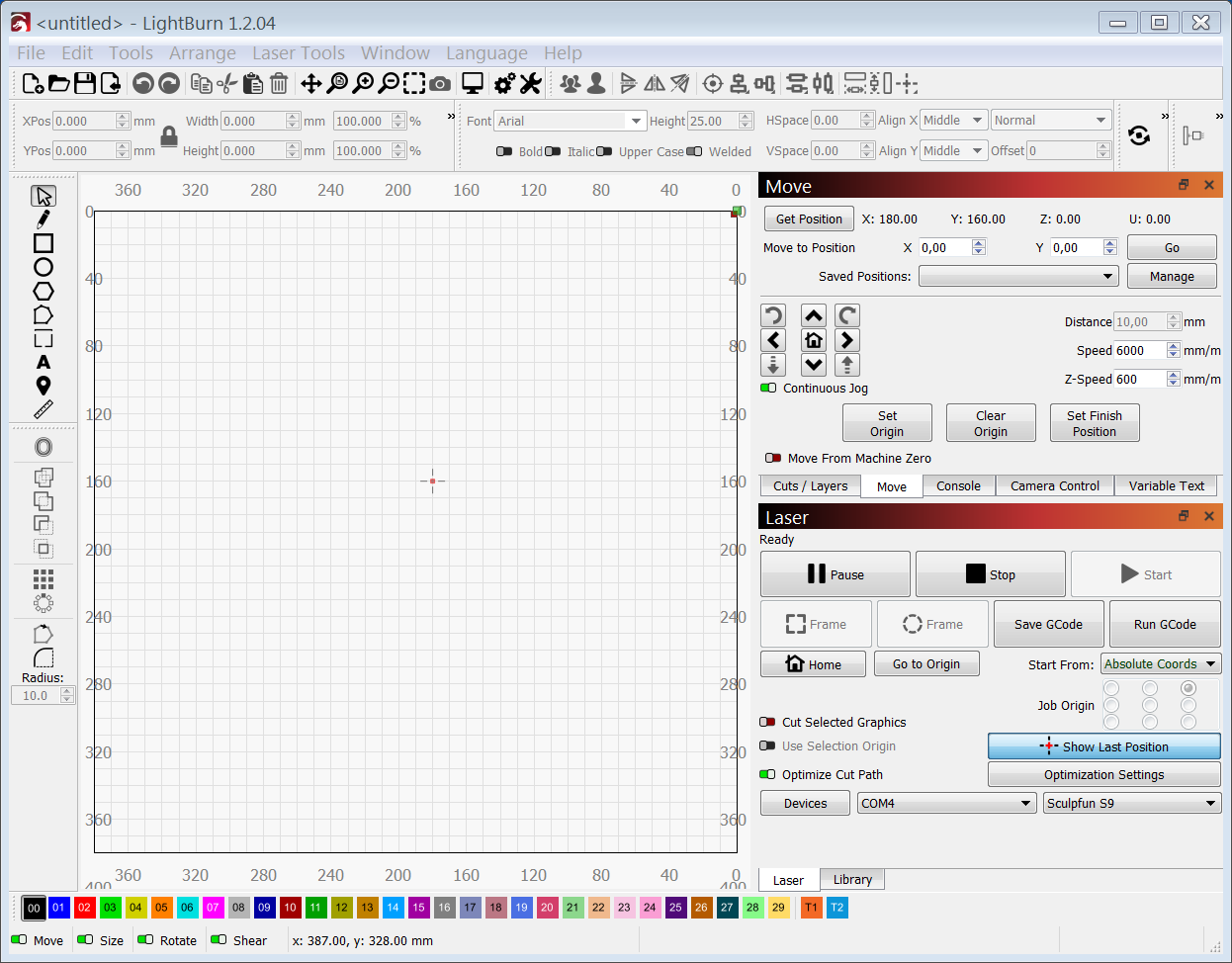
nope. does not work and leads lightburn to a complete nervous breakdown:
→ jogging inverted
→ jogs just about half way in x and y then complains about limits and does not jog again at all
→ afther homing and press ‘get position’ that’s how lightburn looks while laser is top-right
p.s. funny thing is that candle and lasergrbl again work fine with this setting after homing just report workcords 380 380 instead of 0 0 before