I have an xtool laser with the extension. laser bed is 432x940 ( somewhere close to those parameters) running on windows. have set up the camera and done the diagnostics. It shows up and can see the laser bed, the problem that I am having is that it does not put the camera at the 0/0 coordinates for top left. it is putting it at the middle of the bed on the y axis. so it will be at the 0 x axis and 200 on the y axis. how do I get it so the top left corner of the camera area is at the 0/0 coordinate?
I’m either not following or something is conflated here.
If you’re so inclined, open the Laser window and screen cap it (with a screen capture tool like Snip for windows) and then drag that image into a reply here.
The coordinates are separate from the camera image (and set up there) so I’m just not getting it.
Does your workspace size (the grid area) in LightBurn match your extended xTool?
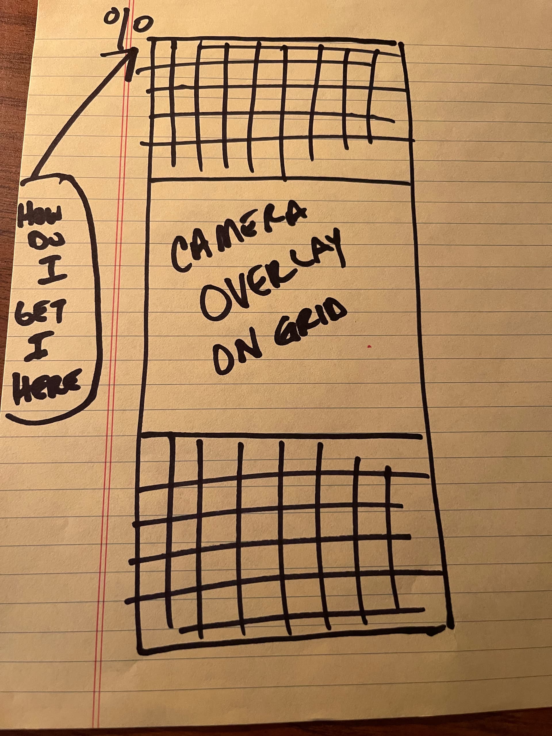
thanks for getting back on this. I will get a photo of my screen tomorrow. I will not have access to my computer and laser until then. I will try to explain better now though. Yes the workspace area does match the xtool extended. So when I set up camera on my new extension set up. I go through the set up camera procedure and calibrate. when I go to make the 4 points for calibration. it moves the camera from coordinate 0/0 to 0 on the x axis and 200 on the Y axis. it does not start at 0/0 like it did previously before I did the tear down rebuild with the extension. I have the camera in the position of the top half of the laser bed. So when I click on camera overlay, it shows the camera overlay in the middle of the grid. So I have a 3rd of the grid above the camera overlay, then the camera overlay, and then another 3rd of the grid below the overlay. so light burn is now acting as the 0/0 coordinate is where the camera overlay is. If I place a piece of wood at the top part of my laser bed. say x=25 and y=25, the piece of wood is in the camera overlay, I then make a square on the to be burned on the piece of wood. When I tell it to start it moves from 0/0 (HOME) to 200 on the y axis then starts it correct moves from there. So my top left corner (where the 1 would be for the calibration) is not at 0/0.
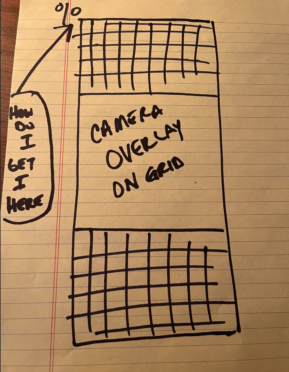
this is a drawing of what I am trying to explain until I can get an actual photo from screen shot.
1 Like
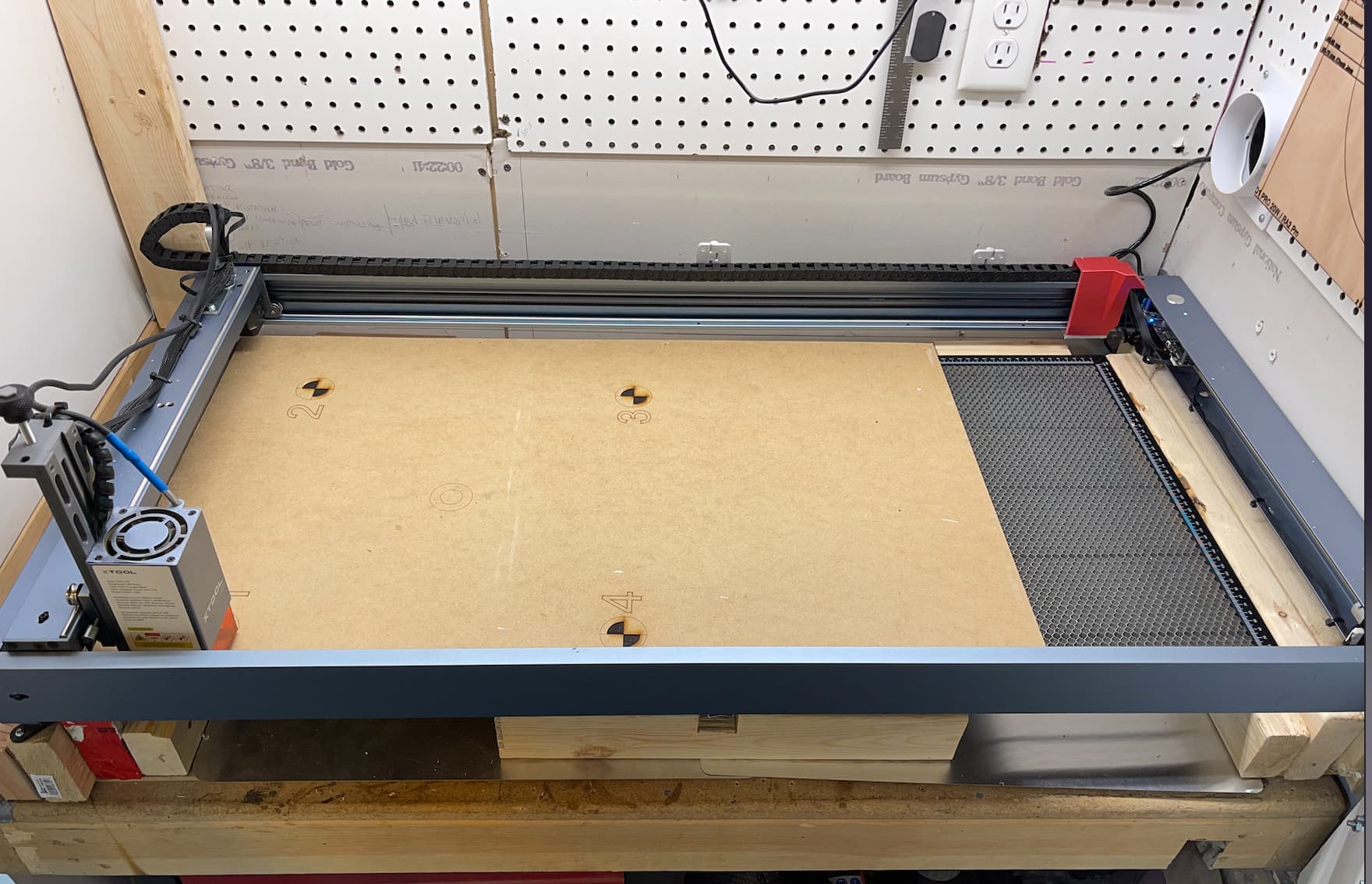
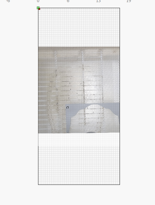
here is actual pics from the screen and a pic of the laser bed where I have the alignment board set up. as you can see the overlay is knowhere close to the overlay.
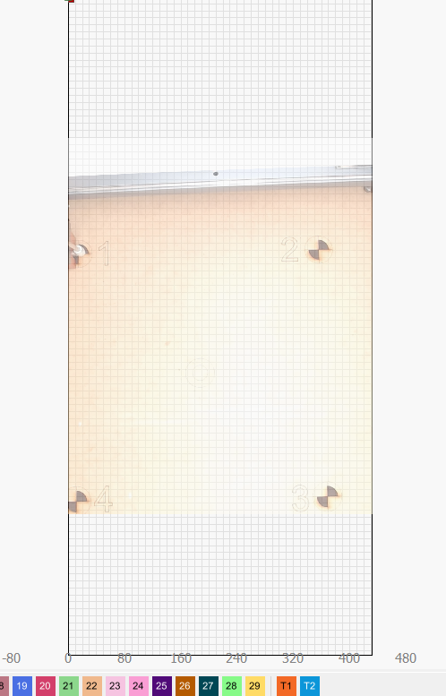
When I am in camera alignment wizard. I will hit FRAME and it will move from 0/0 to x= 19.02 y= 271.02. Hope this helps
When the image is produced by the camera, does it capture the whole bed area?
If you have doubled the axis length you may have to double the camera elevation to capture the whole workspace.
no it does not capture the entire bed, I do not need it to, I want it to capture the top half of the bed. what I want to fix is getting the camera at the top of the bed not in the middle of the bed. The capture is of the top half of the bed, what I want. the image is correct. the place where the laser will start from is not. if I place a piece of wood under the camera and place a square on it to be burned, if I hit frame. The laser will move to y=271 and start from there. If I place an object on the grid the laser runs off of those coordinates (Correctly). Lightburn is placing the camera overlay in the middle of the grid. How do I get the camera overlay and work space to the top of the grid, top left to be 0 x axis/ o y axis? thanks
The limit switches that allow homing may need to be moved to the origin you want.
The coordinate system (origin and axis directions) are set in the firmware. Since the workspace size change seems to have endured - the other settings should be possible as well.
I have asked the Dev team about the image overlay behaviour and I’m looking forward to their insights here.
I have asked for confirmation with respect to how the overlay is applied to the workspace. If the process centers the overlay to the workspace and allows it to be cropped to the shape of the workspace I don’t see a way to move it.
I am awaiting confirmation.
sounds good. thanks for looking into this for me.
I’d suggest using the Y-shift in Camera Controls to see if you can move the overlay to the top.
yeah tried that, that is really for fine tuning, it moved it very little then it stops that has a limit on it. thanks for the idea though
The fellow who wrote the camera software suggested testing the following:
Click the ‘Rotate captures 90 degrees’ switch (bottom left of the Settings window).
Rotate the Physical camera 90 degrees to correct the image to your workspace.
This should allow you to locate the image into the upper part of the Tall-Y-axis workspace as intended.
I get the impression that the images typically produced by the camera, being wider than they are tall, require the software to discard a large part of the image and that this reduces the placement options.
Interesting!
That is not fixing it. It still has the camera in the middle of the grid and it acts like that is 0/0. It is not so if I place something in the grid that lines up with the camera on the piece. It move to where the camera picture is then goes from there to match the cooridinates with the grid as if that is 0:0
This topic was automatically closed 30 days after the last reply. New replies are no longer allowed.