Can I recreate this great raster effect?

I had a user bring me this that they had done on a Universal Laser Systems PLS660 60W, which they were not able to reproduce on the RF CO2 here, even though it’s got tons of power and RF responds to PWM at tens of KHz.

PXL_20211228_071257564

This is a particularly deep color change here. Actually, impossible. It has no physical depth. There are gradiest bars visible on the bottom of my pic that show I can’t make it as dark with the normal process.

So, what’s going on here? Closer look (will get a microscope image soon):

I presume the source file was a bitmap with several “fill” shades. It looks to be halftoning, and offsetting 22.5deg each line. The “on” part is DEEP.

Weirdly I’m not perceiving that the width of the “on” parts’ width is changing, but I’m probably mistaken. They’re clearly deeper though.

So this is creating a visual effect not by pyrography but physically drilling tiny holes, deeper than the width for the deeper shade. It looks like this concept will break down past about 50% black in the original image, as the halftoning will widen the dots until the drill holes physically break the walls and merge and that isn’t good.

I tried, but so far unable to reproduce this deep color. I did try Halftoning, and change the cells per inch to the DPI with the intent to make it offset by 22.5 each line. Played with the line interval too, but so far no equivalent yet.

Any ideas? Pure burn, anyhow- I’m not looking to dust with toner or other enhancements. I’m just looking to reproduce the laser’s burn effect we go on the ULS.

They may be using a different technique but I get some similar effects using the cross-hatch setting. The “art” is to find the right line spacing. As a rule, I use 45 degrees and from 0.2 to 0.5 mm line spacing and turn power down significantly.

Looks like it’s done in ‘Threshold’ mode.

I would think your RF excited machine could reproduce anything a regular hv excited machine could do.

What does the PWM frequency have to do with it’s operation?

Screenshot from 2021-12-29 09-31-52

Mine is currently 20kHz.

:smiley_cat:

I mention RF because the tube’s output power responds very fast, so these are almost certainly consistent with the start and stop points created by LB.

AFAIK the original artwork is bitmaps of large “pixel” rectangles each with their own shade. The offset pattern for halftoning was added by the ULS driver.

“Threshold” would turn this into just a solid black fill, or nothing, based on that threshold.

I’m surprised to see that none of LB’s halftoning/dithering modes appears to work this way, without randomization. It looks like ULS considers the average black value of a “cell” of area around that dot, fires as a dash that gets longer longer based on that value, and the blackest 0x000000 means the dot will be at 100% duty where it merges with the next dot in the line. There’s no randomization.

“Ordered” was closest, maybe, as shown below But I see key differences as shown below. Some prominent differences- LB appears divided/quantified not as growing dashes, but into singular pixels and there’s no gradual increase in “on” time per dot as shading gets darker. Second, why does it favor one line over the other? As I tried larger bitmap scales and it shows a solid shade being represented by 4 types of rows repeating again and again.

Halftoning is quite similar features- not what I expected.

Ordered, Newsprint, and Halftone will produce very ordered patterns. To get the very pixelated look for the graphic you would need to scale it up outside of LightBurn - we don’t have a way to enable scaling that doesn’t also do interpolation (smoothing).

If you use something like Windows paint, Paint.net, or similar software to increase the size of a small bitmap, set it to “Nearest Neighbor” scaling mode, and you’ll get the big chunky pixels. Then run that through LightBurn as an image using one of the above modes and it should do what you’re looking for.

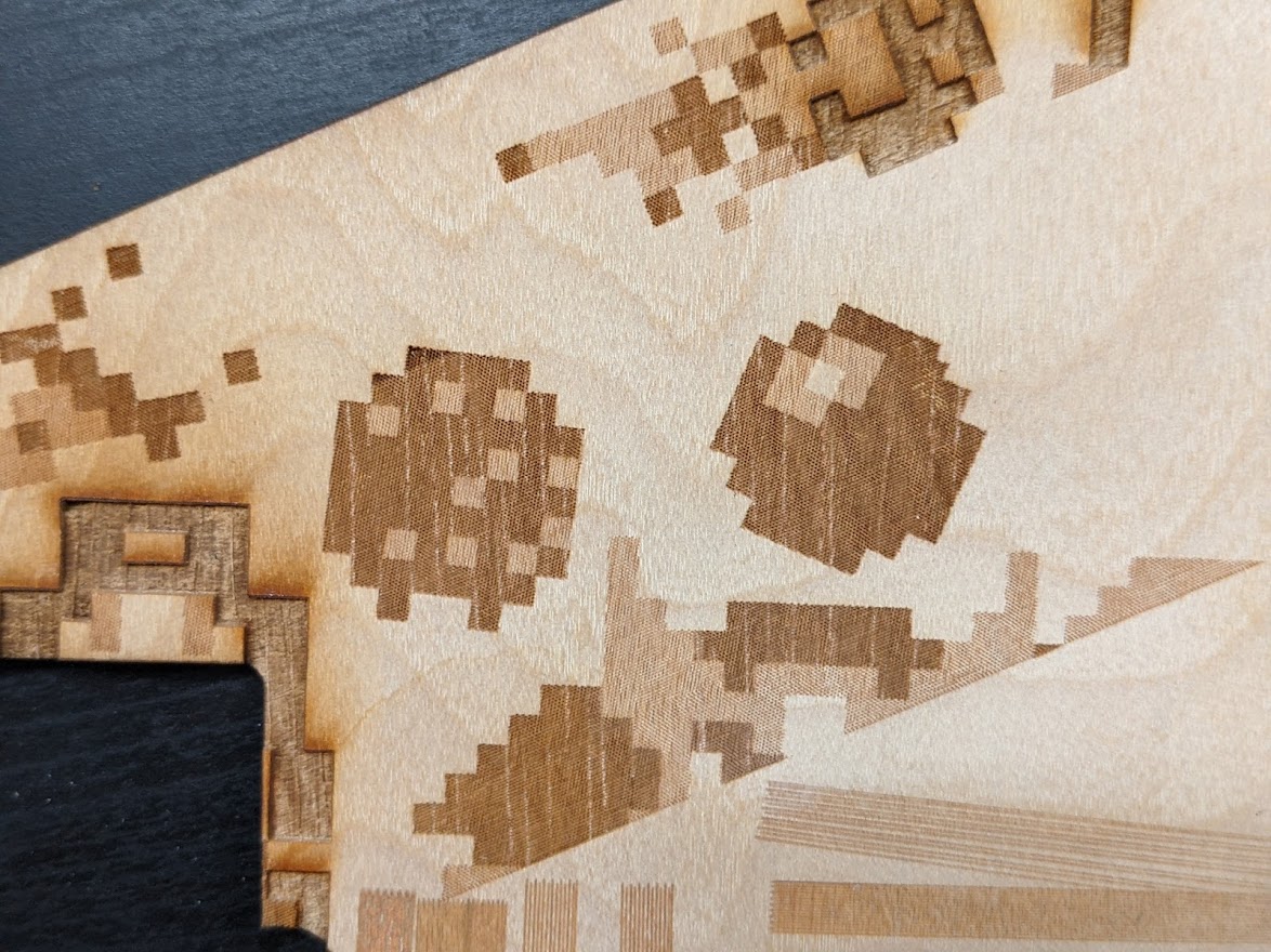
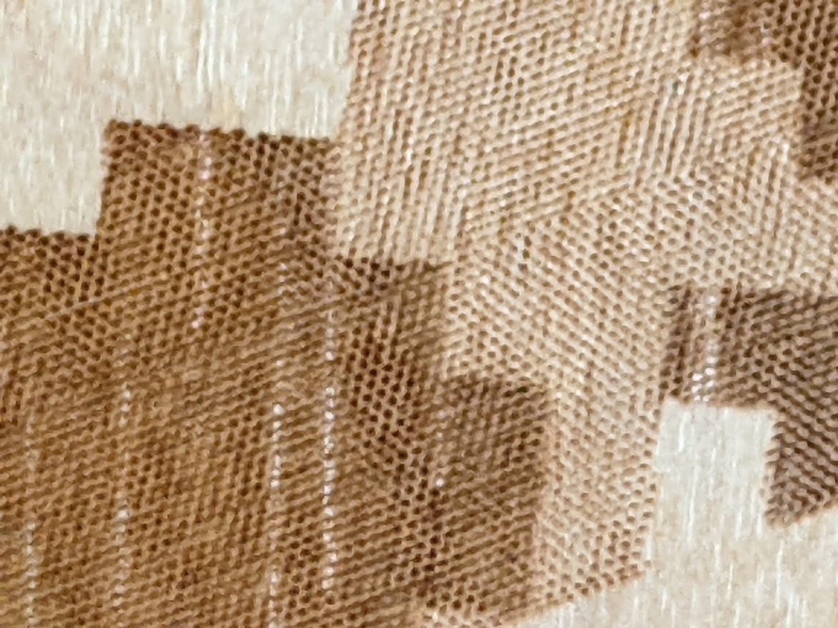
I interpret this to be the opposite. First, let me clarify that the overall appearance as macroscopic, probably 0.25" square- shaded “macropixels” is not relevant. It’s the unusually deep-color appearance within the macropixel. If I did what I call a “standard” fill with line intervals around the width of the beam +/- 50% at various powers, I could not achieve anywhere near the apparent deep color change demonstrated here. The fine honeycomb structure did that. As an added design element which is present but not relevant, the user rotated the 0.25" “macropixel” rectangles by 45 degrees. My apologies if that creates confusion on where the raster motion is happening.

I’ll try to create a more pure example soon that is just regular old shaded squares with no rotation, and not the Mario “8 bit pixel art” of macropixels. I see that this was adding confusion over what’s being discussed.

ULS never tries to build a halftoning “dash” (or dot) out of two vertical lines whose length is calculated from the shade of an area twice as tall. I’m certain of that, often it caused trouble as the line interval also had limited increments- 1000, 500, 333.333, 250, and 100 lines per inch.

The ULS setting is probably 250 lines per inch (~0.1mm line interval) and the dash period is also 0.1mm. I’m guessing the shade is 60% here so the dash length is 0.06mm, and in a lighter rectangle that shifts to say 0.03mm wide dashes.

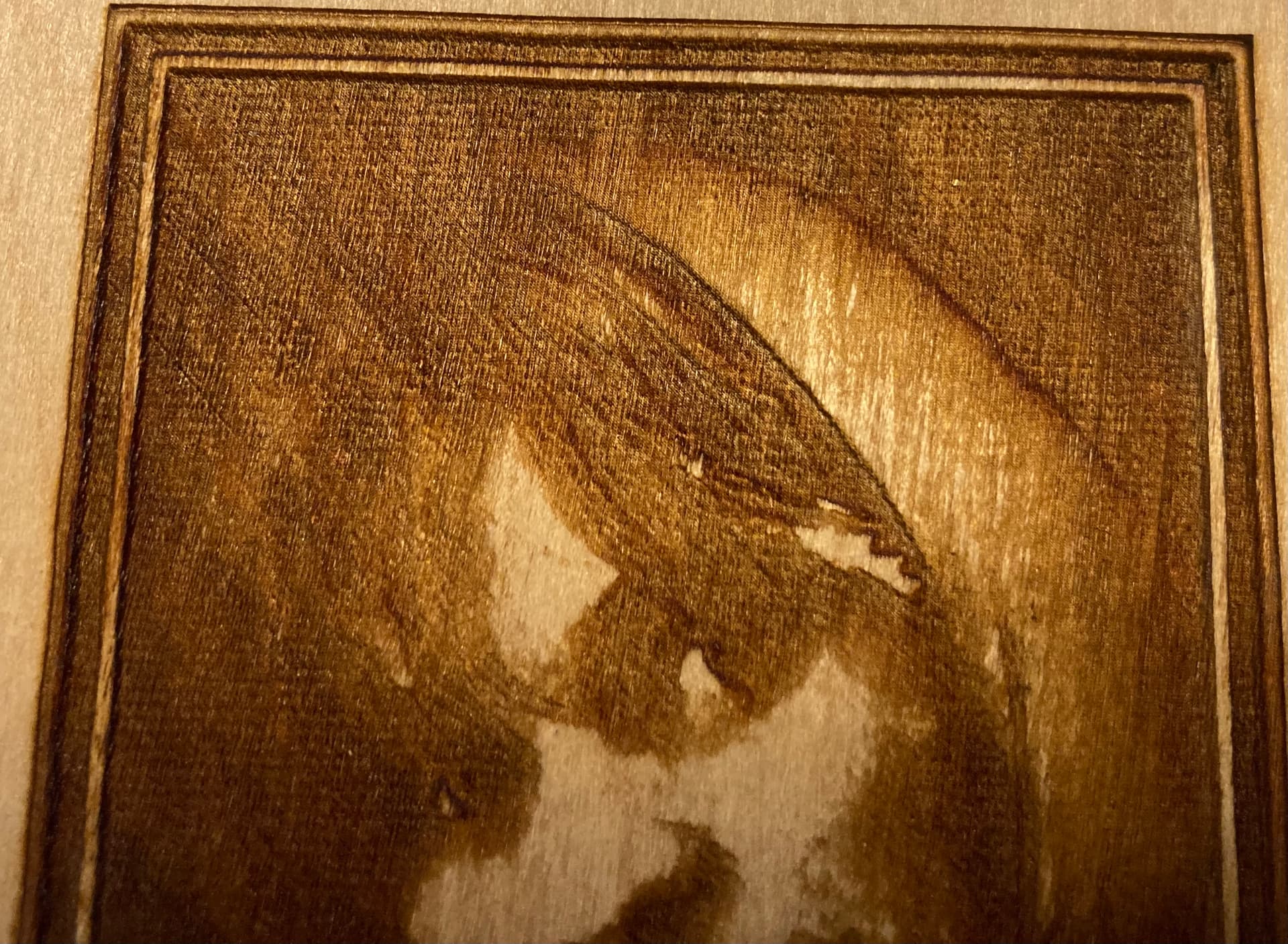
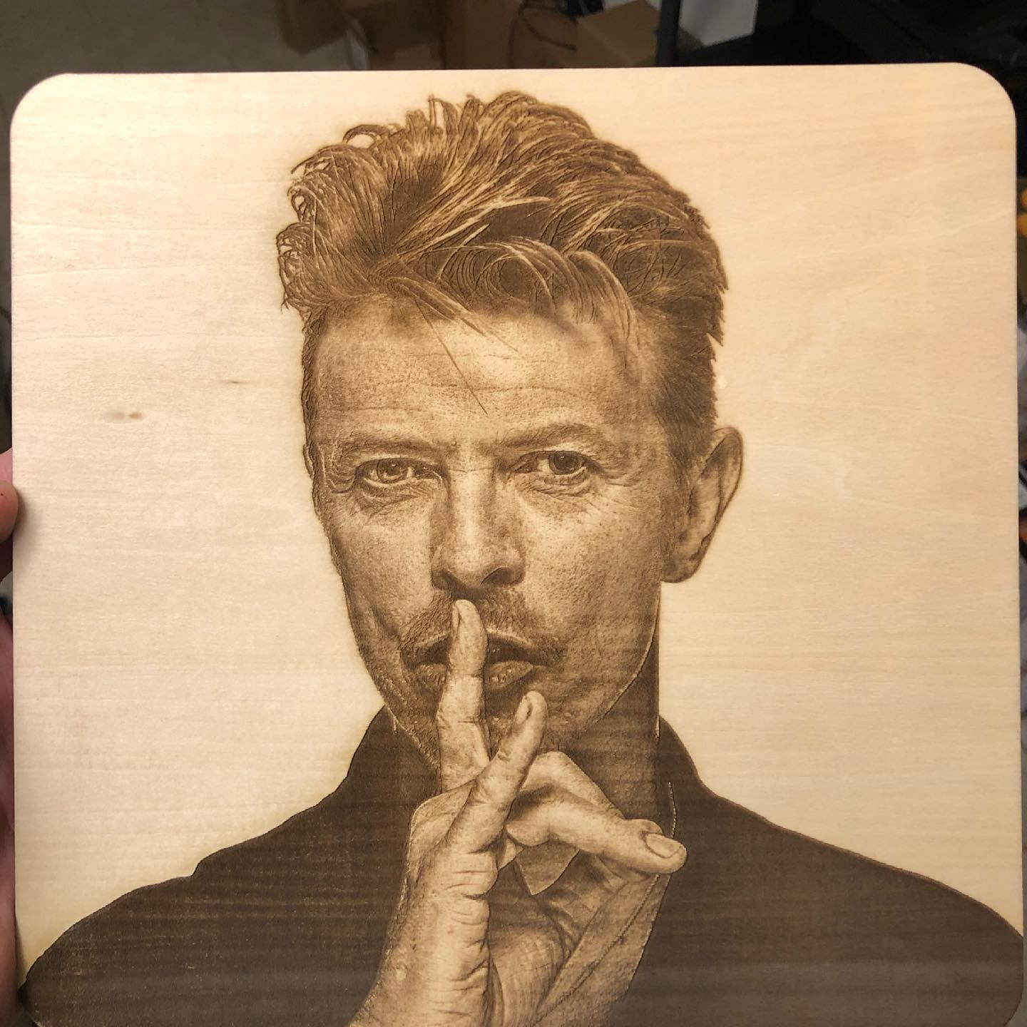
The user was doing this frequently on a ULS machine, and very disappointed that we couldn’t create anything similar on the new system. I’ve gotta say the look they got on the ULS machine was exceptionally high quality, and I’m jealous.

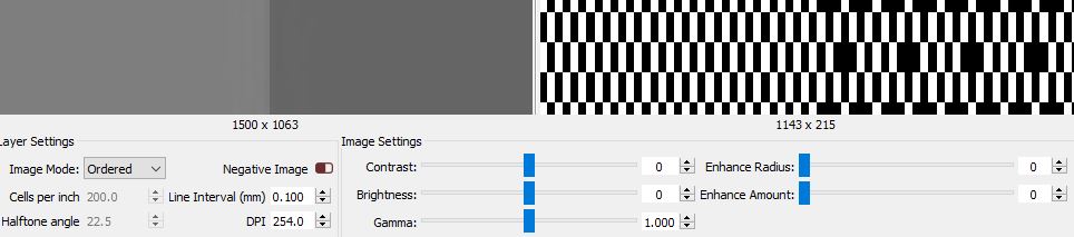
Correct me if I’m misinterpreting this. I see several questions as to the limiting factor here- one, does LB have the ability to do continuously variable-width dashes? I assume the Preview window shows a vertical resolution of 0.10mm, and it appears 4 width quanta make a square on screen. So horizontal is instead broken into a 0.025mm resolution, giving us tall rectangular pixels.

Like I say, I didn’t appreciate how well ULS burned that until now, the appearance is higher quality, and really hoping we can make LB/Ruida do this.

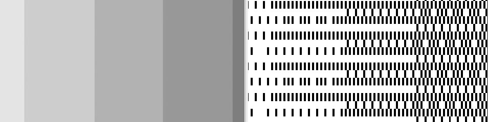
My interpretation of ULS’s halftoning:
The dashes all start at a regular period and that is the same as the line interval, and have a continuously variable width (well, at least enough bit depth to appear so), rather than broken down into pixel quanta at all. The next line is offset by half of a dash period, and the dash period is also fixed as equal to line interval so another way to say the same thing is the offset is half the line interval.

So, the limitations I’m getting is the LB/Ruida system is that it lacks horizontal resolution, and also neither Ordered nor any sort of Halftone/newsprint will do this.

Is this numerically too difficult, and/or would be too much data for the Ruida 6445G? I stepped back and I do see the Preview window might require significant recoding to display correctly if it’s formatting with the horizontal resolution at 4x the vertical.

Oz, you open to external code developers on this? It’s actually an excellent performance mode for lasers I assumed was common, but now I see that’s not the case. I’m realizing this method ULS used isn’t actually “halftoning” as the field defines it, but simple and really exceptionally good for lasers’ raster lines. I can also see a couple of processing options to significantly enhance its capability.

I’ve been observing this thread trying to understand the fundamentals of how this burn is unique as well as reading up on how ULS software operates. Based on the stated characteristics of the burn I’m wondering if this is using what ULS refers to as 3D mode. See an excerpt below. Specifically, the observation that the depth of the “drill” holes being the variable through increased power rather than just the pattern of the dots is what seemed to correlate.

I think what would be interesting is to get some magnified images of the burn so that you could take some measurements in software to confirm dot pitch, dot depth, and dot width for the various gray scale shades. Then translating that to a diagram which you could use as a reference to manually create an example half-tone.

With some trickery you should be able to reproduce the variable power of those shades in LightBurn either as separate layers or power scales. That will tell you if the theories are correct.

1 Like

@berainlb I’m really really well versed in ULS modes. Serviced and taught on ULS machines for years. ULS 3D mode is not the above effect.

ULS “3D” is grayscale mode. However, ULS uses RF-CO2, such as the ULR60 and ULR150. These tubes have no analog input, but a digital modulation input. It PWMs at a high enough rate that the pulses will not show up on any material, and performs as a DAC that appears as analog modulation of beam power.

In acrylic, you can achieve dramatic 3D effects from grayscale “depth maps” as the modulated power for each pixel creates proportional depth.

But ULS’s 3D mode IS just grayscale mode, and can be used to burn high quality 2D images on wood too. It produces notably higher detail since features are not broken down into dithered dots. However, it’s somewhat tricky to tweak the dynamic range- low power produces no color change on wood until a certain threshold that varies with raster speed, then an increasing shade of deeper brown, then starts actually cutting deeper for blacker pixels but this don’t actually appear as a notably different shade and the depth is mostly pointless. So, like grayscale mode (which it is), ULS’s “3D mode” requires some tweaking to get a dynamic range of shading burned onto wood from a photo’s grayscale values.

1 Like

Ah… that must make you doubly vexed that you can’t recreate the effect.

I knew that the 3D mode was used for more dramatic effects but saw, as you state, that it could be used on wood to achieve power modulated deep cuts.

My idea for manually creating a similar half-tone I think would still hold if the only variables are dot pitch, dot depth, and dot width.

1 Like

Well I did spend awhile pondering whether we could ever do external quasi-halftoning like ULS uses, create a 1-bit image and pass it through to LB/Ruida in either grayscale or threshold. I tried something similar on ULS. I do not believe this would work on LB/Ruida, however.

Well for starters, your image resolution has to match the line interval exactly. This means you cannot change an imported 1-bit bitmap image size in the job without breaking it. Very few users would be able to understand and manage this, along with jumping back and forth with another tool.

But what I see is that if I’m using a 0.1mm line interval, create a 254 lines/inch 1-bit image, then that’s still not going to do it. The horizontal resolution is still 0.1mm, so there’s only 3 shades possible on a dash 0.2mm wide- it can be off, one pixel on, or two pixels on.

Could I bump the resolution to 16x of the vertical line interval that in the 1-bit grayscale image, and lengthen the dash so it can be 0 to 15 pixels wide horizontally based on the original image shade in that area? Well, for one, that’s crazy to set up and I don’t think I can make a photo tool convert in this way, it would take a custom command-line tool I think.

But even if I could create that, I don’t think LB would handle it as hoped. bitmaps are square pixels, this would be passing a 4064pixels/in resolution bitmap into LB, it cuts with a 0.1mm line interval and I suspect it will resample along the way rather than resolving to only look at every 16th line and ignore the other 15 completely. I do know grayscale resamples the image to the line interval, including horizontal resolution. So that won’t work. “Pass Through” mode might if LB doesn’t try to resample the horizontal resolution but I don’t know, the Preview window does not work with Pass Through I’d need to be at the machine with a microscope.

But I’m not sure. I might need to draw a pic, I know I’m not explaining it all that well. It’s still not a practical way to handle it since it’s wildly complicated to use.

1 Like

Turn on pass-through in the image settings and LightBurn will force the output to be 1:1 with the input pixels, regardless of the size of the image. The setting exists to allow users to run externally dithered images from things like One-Touch and PhotoGrav.

I think you are dramatically overthinking all of this and you just need to play with settings a bit. Getting a dark engrave generally means going slower and with lower power, so the material darkens more than it vaporizes.

The choice of wood also makes a big difference - Birch doesn’t darken nearly as well as basswood or alder, for example.

If you want “chunky” patterning, Newsprint and Halftone modes are what you’re after. Halftone needs about 5 or so pixels per cell to be able to do adequate shading, so keep your “cells per inch” to about 1/5 of your dots per inch value (or less) to get good shading. You might have to increase your DPI to get the look you want. You can lower the image Gamma value to compensate for the increase in dot overlap to preserve mid-tone shades.

It’s not hard to get shading with LightBurn:

That was done with a glass tube 60w CO2 with a 1.5" focal lens.

2 Likes

Hello Oz! I didn’t want to nag on this over the break, I know you guys were off for the holidays.

Oh I can do great photographic rasters! And I know about contrast agents (baking soda or borax). There are plenty of great rastering alogorithms here, and we have been making great burns.

Let me clarify- this isn’t about “chunky” patterning. It’s about fine detail and also unique shading effect that starts at a microscopic level and primarily occurs with this algorithm. The overall “pixel art” plan for the piece is not what this is about at all.

For the specific benefits to occur, we don’t want cells made up of multiple lines. Each line is its own, with a start point shifted one half cell each time, and a high horizontal resolution, numerically.

I think you are dramatically overthinking all of this and you just need to play with settings a bit
Oh all the best things come from overthinking!

This particular ULS halftoning algorithm has several major advantages, and the more I think about it, it’s uniquely suited for the way lasers cut raster lines. We did have a discussion and quickly reached a consensus that we cannot convert this ULS machine to Ruida/Lightburn until this capability exists. Users have become accustomed to this mode, it’s a unique high-quality effect we need to maintain.

  1. This represents somewhat more detail for the same lens and line interval than other dithering algorithms, if you are actually burning photos. That being said, ULS is not actually implementing this to full effect either, because there is only a few choices for Line Interval (represented as “Quality” or “Image Density” steps) and also no control over the horizontal dash interval.
  2. There are effects you can create by punching pixels with depth. Is it the only way? It is the best and no one should ever use another method? Of course not. But, what this does appears to be the best at preserving the material’s structure remaining in each line. If we have the normal offset per line and the dash period is limited to 50%, I see that makes the best case for representing detail while maintaining the material’s structure with deeper burns, as it leaves a wide unburned dash that is notably wider across than any other halftoning method attempting the same level of final detail.

And it actually seems pretty simple! ULS wasn’t packed with a lot of computational power, and have been using it since at least the early 2000’s. And again, ULS didn’t even do it “right”, either, as we need more control over the vertical line internal and ideally the horizontal dash period.

I can clearly see the algorithm this needs, and I think it has performance advantages over any of the other halftoning methods and seems to be a very high net return for the effort. I know you are a small dev team, but I’d definitely like to advocate for this feature enhancement. Some of our other users will say the same.

Thanks!

I think a diagram of how you see the ULS half-tone working in contrast to current methods would go a long way to relating the impact.

Is there a way to extract the ULS half-toned image for more thorough review and experimentation?

Would be ideal if a proof of concept could be generated even if manually.

@RalphU We have a couple of ULS machines. One’s a PLS660 60W, but the NEAT one is a 32x18 ULS machine rebranded “Royal Mark”. It’s the same frame in most respects as the PLS/VLS and similar XY gantry. But it’s loaded with a Coherent Diamond G100. The original Diamond G was dead (like dead-dead, the service records showed a very troubled history), but I pulled a Diamond G100 takeout from a more recent Epilog machine and it does perform with a 100W output. It’s water-cooled metal RF-CO2 tube and they respond very fast and respond with linear scale of output power down to very low % duty cycles.

I don’t have an HPDFO. We use 2" lenses. I am very familiar with all the properties and math of different focal lengths and HPDFO. Actually I have other lenses, but 2" is pretty much all we need.

I mostly use a Photoshop action that is pretty old called the Gold Method, but works pretty well. Maybe you could write a Photoshop action to do what you want.

I went through that- I don’t think it’s possible to do this externally/manually and burn as “pass through”, as suggested. Several things break it. One, the halftoning rows need to line up exactly with the line interval and avoid aliasing. It cannot be resized and run automatically in LB without breaking that. I’m not even sure how to create a resolution that may be “fractional” in lines/inch. It needs to offset every other line by half the dash period.

More important, the dash period cannot be readily represented by a pass-through bitmap at all, because the horizontal resolution is different. Consider this:
Say we have a 0.1mm line interval (more often I’m more like 0.12mm to 0.175mm, but it’s easier to show math starting from this). The horizontal dash period is 0.1mm (but ideally this could be varied by user)
At 50% black, the even lines are “on” for 50%. So the beam’s firing pattern is 0.05mm on, 0.05mm off (actual burn pattern is going to be pill-shaped and a different discussion).
The odd lines are the same but start offset by 0.05mm so they don’t make obvious vertical lines.

“So just create a very manual process to make a bitmap with 0.05mm resolution”. Well, that’s not it. Vertically, yes, we have a 0.1mm line interval. The dash period is 0.1mm, but that’s only for the start point.

This halftoning can represent (probably) 256 shades with zero randomness by varying the end point. At 0% black, there is no fire. At 100%, the line is not dashes but just a continuous burn line. At a gray value of 79 of 255, the dash “on” period would be 0.031mm. That can’t be represented by 0.05mm pixels, nor 0.025mm, 0.0125mm, etc. So the endpoint is more or less “continuously variable”, even though the line interval and dash start points including the odd-line alternating offset break down into a 0.05mm grid.

Could you just externally make a bitmap with the desired resolution then that can represent these dash periods correctly? Well, looks like a no. The document would have to be (0.1mm / 256) square pixel size to represent the continuously variable endpoint. The start points of each dash would be spaced by 256 pixels horizontally, and 256 pixels vertically anyways, but that endpoint variability to represent the shade is problematic unless we massively over-resolution it.

At some point of course, hardware limitations come into play. Numerically, the controller has quanta of time and X motor steps that will probably be a limiting factor here, but it’s not critical to actually resolve accurately all the way down to 256 different possible widths on the dashes. It’s still got great advantages before that

I’m thinking what the best way to illustrate this is, and also how to explain why this method offers distinct advantages that cannot be done with existing dithering/halftone options. Wish we were in person in the same room.

So I think there’s two approaches to graphics here.

One is straightforward color change, which involved little or no depth cutting. Raster lines generally need to be spaced as close as possible for the burn spot side. At that, the ULS halftoning- again, not even that well implemented- is capable of higher detail for a given line interval and spot size than anything LB currently offers.

But there is also considerable value in structural burning, which is what my second pic (microscope) is showing this is. It is deep holes, which requires the line interval actually has to be greater than the spot size. If too close, the wall disintegrates, leaving only a regular carved-out fill area. And often inconsistent as it breaks apart in some parts and not others.

This is ONE area where ULS halftoning is the only way to go. By using a regular period of single-line dashes and offsetting, it leaves a matrix of the absolute strongest wall possible as long as the period is under 50%. It neatly avoids placing a burn from one dash ever being adjacent to another dash on the same line, or the next one. Thus, structure.

I played with it some more, went to extremes, and curiously made graphics that looked subtly different if viewed at a different angle. If you’re above or below (raster lines oriented left and right), then you aren’t looking down the holes and the image isn’t as dark.

Still got a high demand here to reproduce this on a LB/Ruida machine, and it’s proving impossible to do manually since it comes from a very low level within the software.

This is gold, it’s the little things. Ty

1 Like

I’d really like to bump this. This would be a big upgrade for LB, and essential feature for us to convert our remaining machines, and can’t be done without the feature being integrated into LB. How can we move forward on this?

You might try going to

And see if anyone salutes…

:smiley_cat:

RDWorks does not resample the input image as far as I’m aware, and if you give it a 1-bit image, and tell it to output every 16th line, it will do so. The horizontal resolution is preserved if I’m not mistaken. As I mentioned, we did this at one point, but found that the aliasing produced in normal images was horrid.

If it doesn’t do resampling, it would be usable to verify whether this is the magical unicorn of image engraving you believe it is. :slight_smile:

I, for one, am looking forward to the burn-off.