I’m in the process of putting together an OpenBuilds Arco 1010 with BlackBox for pen plotting now, and perhaps laser use down the road. My application is basically very large format advanced pen plotting. I need a solution to convert detailed vector art I create in Adobe Illustrator in to gcode to drive the 1010’s controller. This is illustrative work with hundreds (if not more) of mostly open ended line art which I need to convert and drive a fine line pen. So far I have not found a workable solution. The question is, can I use Lightburn by pretending the pen tool is a laser and incorporate/translate laser on/off action produced by Lightburn to drive a servo via PWM? If no PWM control available from . Lightburn, I know how to convert an on/off in to PWM if necessary. If you are wondering - passing an Adobe svg file thru Inkscape’s gcodetool extension might have worked in the past for simpler illustrations, but serious limitations and workflow problems with the current plug-in make it unusable for me. (it has not kept pace with the latest Inkscape releases) Can’t use Openbuild’s CAM gcode converter app either because of issues with it handling open ended vectors. As a result, I’m forced to look for a reasonably priced, workable 3rd party solution. My question is, can I realistically adapt Lightburn to generate gcode for Blackbox to run a pen plotter via its Grbl firmware, with a ton of open ended vector paths, and do it on a Mac?
This has been done before, yes. I’ve done it with an Eleksdraw machine. @adammhaile - You did this with the Engravinator, right?
How did you config Lightburn to drive the up and down pen servo on Elksdraw? Can LB handle hundreds of open ended vector path lines in an svg file, scaled 100% exactly to match the adobe file contents. To add a bit more info to my app, the pen plotter must plot lines accurately, as if it were a laser in a way, flawlessly, as an overlay on of artwork made with another medium below. The artwork below risks being ruined if the plotter screws up.
@AllanArt - It’s possible to use LightBurn for a pen plotter but there’s no way that I’m aware of to do it with a machine like yours that has an actual Z axis. Both @LightBurn and I have only done this with a servo pen axis. In my case I have custom grbl firmware that translates the M3/M5 spindle/laser commands to servo output and with drop/lift the pen accordingly. But there’s no way to get lightburn to actually output Z movements for your machine (assuming you were just going to attach a pen to the Z axis).
@LightBurn and I have discussed allowing custom gcode output (for example, replacing the laser on/off commands with whatever gcode you wanted) but it’s not even on any roadmap. Just something we’ve talked about doing at some point - it would not be an easy task.
The only way I can think of doing it now would be to save the gcode from LightBurn and then post-process it with a script that would replace M3 with a Z down move and M5 with a Z up move.
@adammhaile - From the original post - not a stepper, but a servo:
As for “can LightBurn handle hundreds of open vectors”, yes, trivially. This file, for example, contains over 100,000 open shapes:
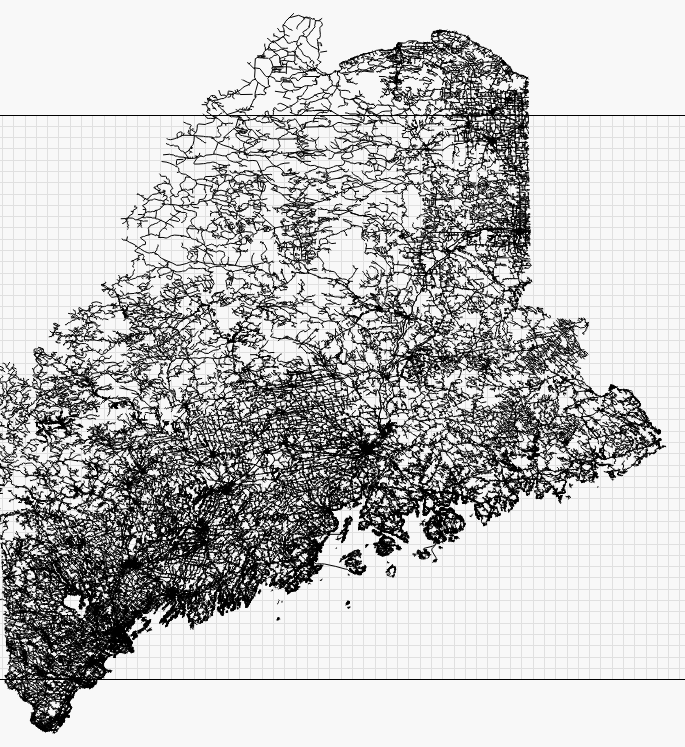
Optimizing the cut plan takes a while, but partitioning it into groups and using Order by Group first helps that quite a bit.
My ACRO 1010 does not have a Z axis connection. No Z direction gantry. This machine config is used primarily for laser and 2.5D cnc apps. I wish to adapt it for a large format pen plotter with gcode controlled up and down action for the custom pen holder I am designing/printing - via servo action. The Blackbox Grbl controller for ACRO provides a PWM output to drive a servo, but with limitations. It’s not clear to me yet if I am forced to use their CAM software (gcode generator app) to get proper gcode servo travel action gcode, but nonetheless I can’t use it because it is not equipped to deal well with hundreds of open ended vector paths - for openers. That said, their controller hardware does provide an adjustable 0-10v “tool” logic level output. I’m not sure, but I believe this tool output level is used to control the power of a laser or other analog tools. If so, my question is can this output be restricted to just two logic levels, on/off, by LB? If so, I think I can design a small circuit (using a 555 chip) to translate on/off logic in to a two state PWM signal to drive the servo. Alternatively, I could design a circuit to drive an on/off solenoid action instead - although their is an electronic hardware downsides to that method. So back to my question again, can I get LB to generate a logical on/off tool action in the gcode, that it would produce from an Adobe svg file? An action that would be in one logical state while the laser head is OFF (not drawing a pen path) and the other logical state - ON - when the laser (the drawing pen) is tracing an open ended vector path? I’m thinking since OpenBuild offers LB in their parts store for the ACRO, I assume it generates gcode to access the BlackBox tool output in sync with the plot. Is that the way it could work?
Right, right - sorry, I knew that when I started responding and seem to have lost the trail part way through.
@AllanArt to clarify - the only way to do this is to change the grbl firmware of your machine. There are a few out there but grbl does not inherently support servos. Yes, servos and lasers both use PWM but not in the same way. You would likely have to swap the firmware every time you wanted to use the pen instead of the CNC spindle because, as far as I’m aware, there’s not a great way to do it without blowing away support for the other. Lasers as it is in grbl use the M3/M4/M5 spindle commands, but with “Laser Mode” turned on. The assumption is that you’d not have the spindle hooked up when using the laser. But when you use firmware that supports servos, it will generally ONLY work with a servo. There’s two types… one that simulates a Z axis (this will not work with LightBurn) and others that respond to the spindle speed commands. This will work with some extra config in LightBurn.
If you are willing to reflash your firmware, let me know and I can walk you through what’s needed.
@AllanArt just saw your new response that came through while I was writing the last one. Ok… no Z. Great. Then yes… you can do this but you will need custom firmware.
You are in luck… I’m literally, this very moment, in the middle of writing up docs for using my Engravinator as a pen plotter, along with the necessary firmware changes.
Be back soon with details.
Just saw the latest post. Thx. I don’t have that many paths, but there are a lot. Mostly in the hundreds, but occasionally a thousand or so. I have the option of organizing these paths in layers in Adobe - and/or layers with different colors for each layer. At most I would have 3 layers, but more often just one layer. Remember, in the end I will more often than not plot fine lines with a .05 black multi-liner. Things that are very important to me are 1. The pen can never lower on to the plot surface unless it is tracing a vector. A pen up/down synchronizing mistake will result in a ruined piece of art below. As such, must have a gcode workflow that does not rely on me hunting down lines in a gcode code script to make manual edits. 2. It’s scale must be accurate and adjustable if not. For example, say I create a 300 x 200mm rectangle in Adobe, the plot needs to be exactly the same - or I must be able to “tweak” the XY scale such that I can make it match.
You are more likely to have scale and position issues with the physical hardware than you are with LightBurn. LightBurn does not issue a laser on command unless there is a line to draw, so unless your pen lowers in response to other commands, you won’t have an issue there either.
The OpenBuilds Cam gcode generator will choke on large vector files as it is essentially a web page running Javascript.
It’s worse than that. While you can simultaneously collect a group of vector objects to give the gcode assorted path parameters, that only works as long as the vectors are closed paths. Otherwise you are forced to collect them one-by-one for open path vectors. That is also unworkable for my application.
LightBurn really doesn’t care if paths are open or closed - the only thing that affects is whether they’re inside / outside sorted (if you have that option enabled).
If I understand how LB controls a laser, it’s using PWM values to control the burn. That would seem to be a good thing in my case - if that PWM action in LB gcode drives the Blackbox PWM output without having to jump thru a text editing hoop to make it happen. I would think since Openbuilds offer LB as an ACRO option, there is a firmware build in the pulldown list of builds in their Control interface app that provides for this - but I’m guessing at this point. If that aspect is true, my next question is - can you set LB to deliver only two PWM values to equate to on/off. If that is true but the PWM values are not proper for the pen holder action, I think I can design a PWM circuit to intercept it to convert it into two values with the proper range for the pen holder. I would not expect Blackbox to inject some kind of idle errant PWM state when no file is loaded, but one thing is for sure, the plotter must always deliver a “pen up” PWM value the moment the plotter is turned on. That must be its normal resting state. Same must be true when a gcode plot from LB is loaded. From that point on, the only thing that will enable/allow the pen to lower is gcode in the LB generated plot that will call the “on” PWM state, but only when drawing a path. In other words, can I configure a laser plot in LB to deliver “binary” on/off values for the PWM output in the gcode and no value(s) in between?
LightBurn doesn’t deliver PWM values, it just generates GCode with spindle speed values set, and unless you’re using grayscale, you’ll get “off” and “power” where the 2nd value corresponds to whatever power value your layer uses.
Many of your questions can be trivially answered by just installing the software, setting up a GCode device, saving some GCode and looking at it in a text editor.
You are probably right. I plan to download the trial version once I get back from a trip next week. At that point my next question will be, do you include the acro 1010 as one of your machine device choices and/or what is the proper device to choose to best fit a laser plot to a pen plot?
“Acro 1010” is a machine, but LightBurn only cares about the controller / firmware. GRBL is the firmware it runs, and we support GRBL. GRBL-M3 is likely the best choice because it generates the simplest GCode.
One last prelim question. I read in the LB manual something about its coordinate system being a +X +Y coordinate based plot area, with the origin in the front left corner. Blackbox firmware uses a ±X ±Y Cartesian system with 0,0 in the middle with the ability to mark 0,0 elsewhere independent of the loaded plot file. Will I run into a problem and have to edit the LB gcode file manually to resolve this difference?
You’ll just need to use a workspace origin offset to move it to the front left. Read here: https://github.com/LightBurnSoftware/Documentation/blob/master/CommonGrblSetups.md#common-grbl-setups