Hello,
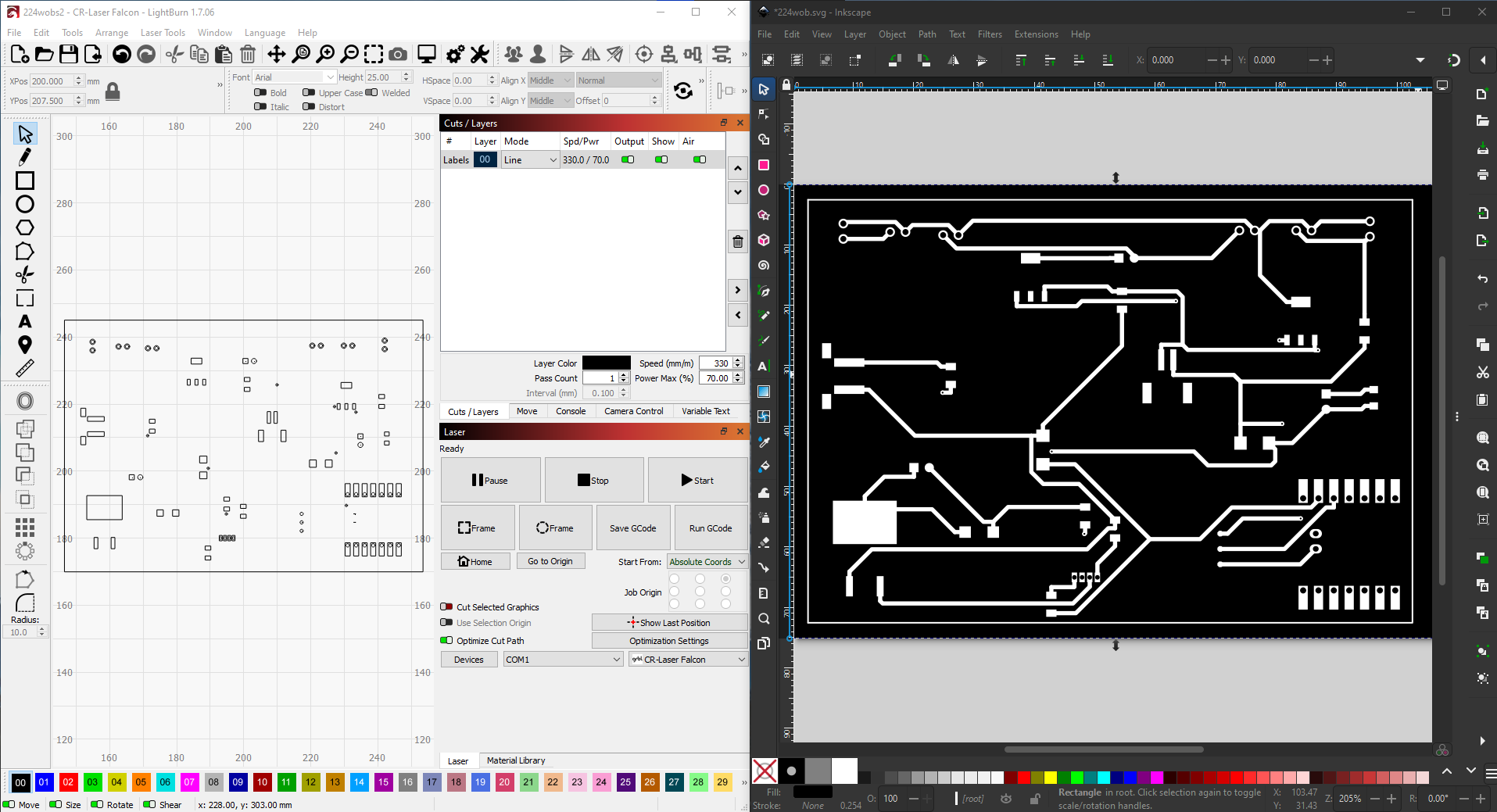
I am new to Lightburn and trying to etch my first PCB, I have the image as a SVG and it shows perfect in other software but does not show the copper traces that are in the image it only shows the pads. I’m sure it’s something I am overlooking but I have tried different ways to import this and different file formats, but I cannot seem to find the right combination. Any help is appreciated.
Can you send your svg or the format you are trying to import?
Yes of course.

There is some setting in inkscape that doesn’t fit, but I can’t find it. (There are some users here who are experts in inkscape, they will probably come up with a simple explanation ![]() )
)
The only thing I can manage is to trace the copy in LB, but that is not the point of your projects, more of an intermediate solution when nothing else is available. However, it requires a lot of manual work to be precise.
The best solution would be to find the settings in inkscape that make all elements/layers expotable.
If you’re designing with Kicad, this is a known problem due to the way Kicad creates the SVG file.
Previous discussions may be helpful:
https://forum.lightburnsoftware.com/search?q=kicad%20svg%20import%20order%3Alatest
Exporting the design using a different file format may produce better results. Apparently some folks convert the Gerber files into DXF (or some such) with an external utility.
1 Like
This was actually created in easyeda.
Now we all know! ![]()
Their Export doc doesn’t give many choices. Obviously, they want to capture the whole chain.
PDF might work, but it depends on what PDF features / functions / primitives they use.
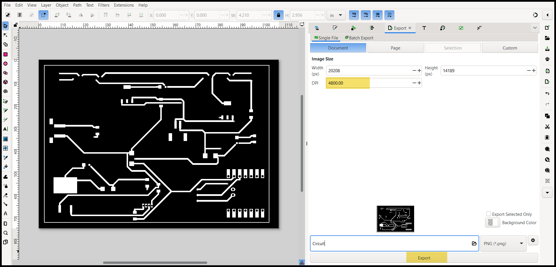
I’d try tracing the PNG export, assuming they will produce the file with at least 300 DPI resolution. If you can get a higher resolution, that will improve the accuracy of smaller features.
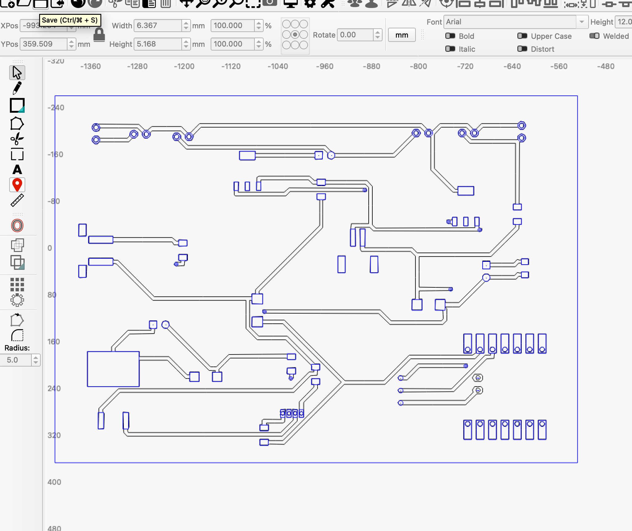
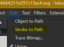
In Inkscape if you select All ( Ctrl + A ) with your svg then Stroke to Path:
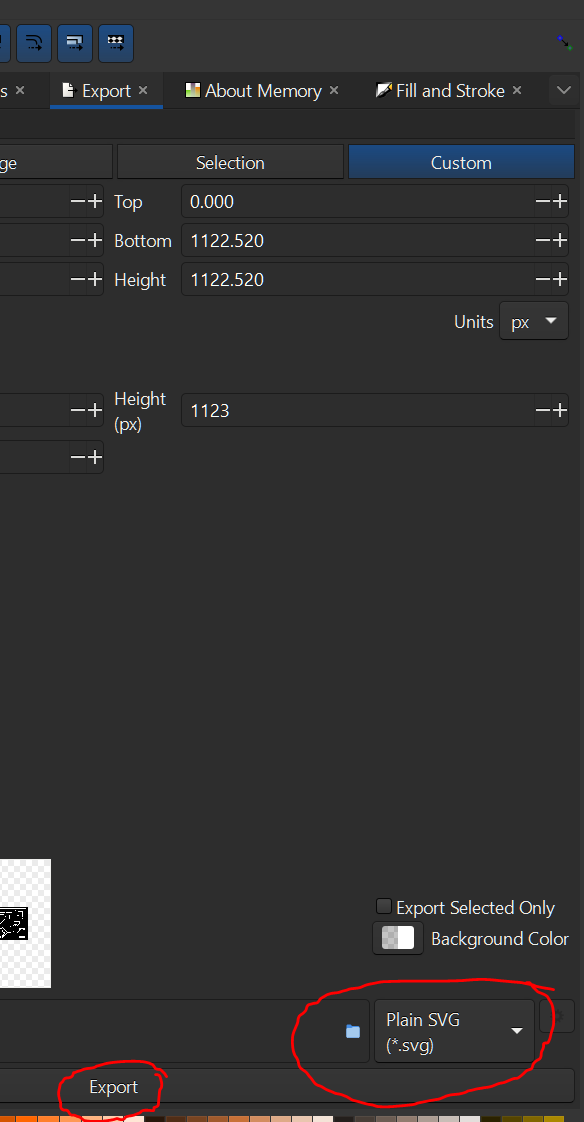
After Export as Plain SVG:
Drag the file into Lightburn:
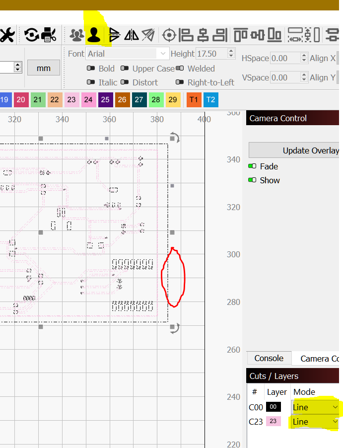
Ungroup, select only the outline and set to a T1 or T2 Cut/layer.
Set C00 and C23 to Fill mode.
.
Then you can edit the shapes.
.
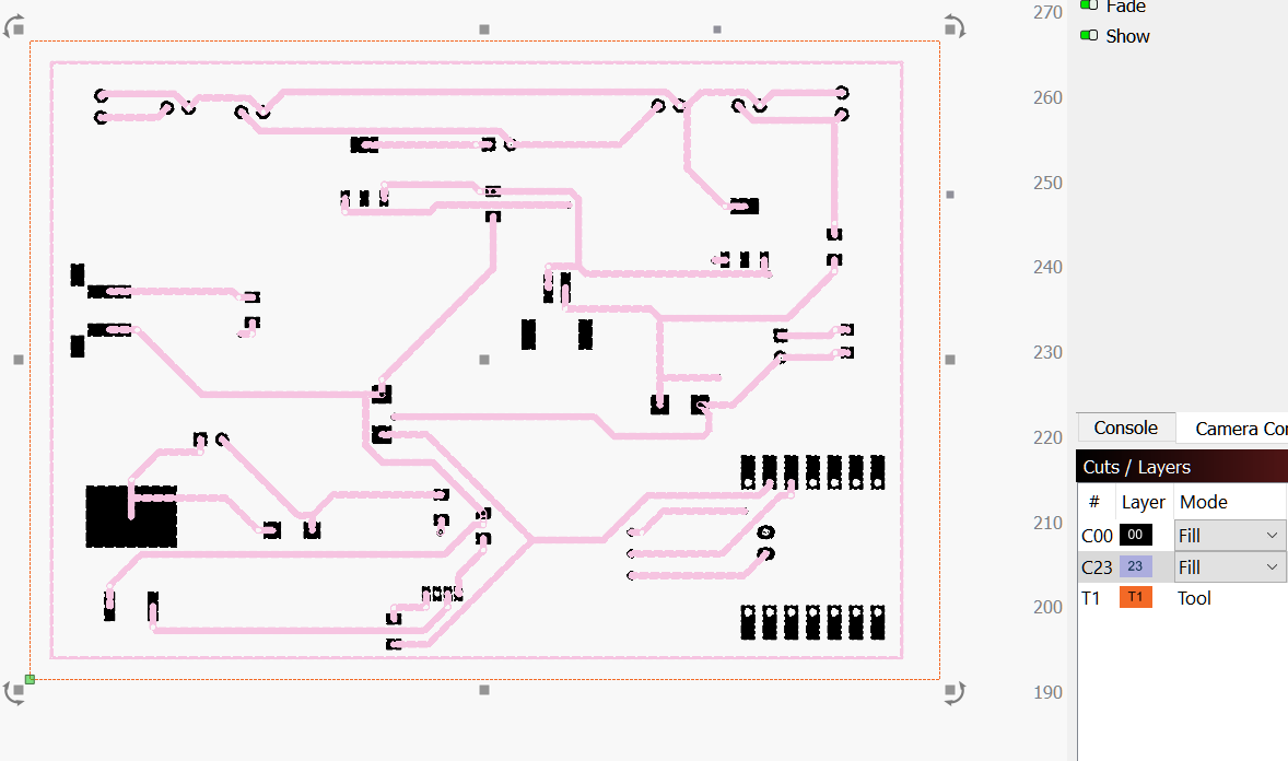
Example:

You can set everything to the same Cut/Layer but T1 and you need to design the tracks to connect to the pads outside to avoid a lot of editing.
1 Like
Is this what you are looking for?
Circuit.lbrn2 (78.9 KB)
… only missing a proper explanation, then this problem is solved … ![]()
Yes I believe that is what I am looking for. I’ll use this to create a board and see how it turns out. Would you share steps please.
I have access to a program called Cuttle, that imports SVG, and has a flatten command that works well.
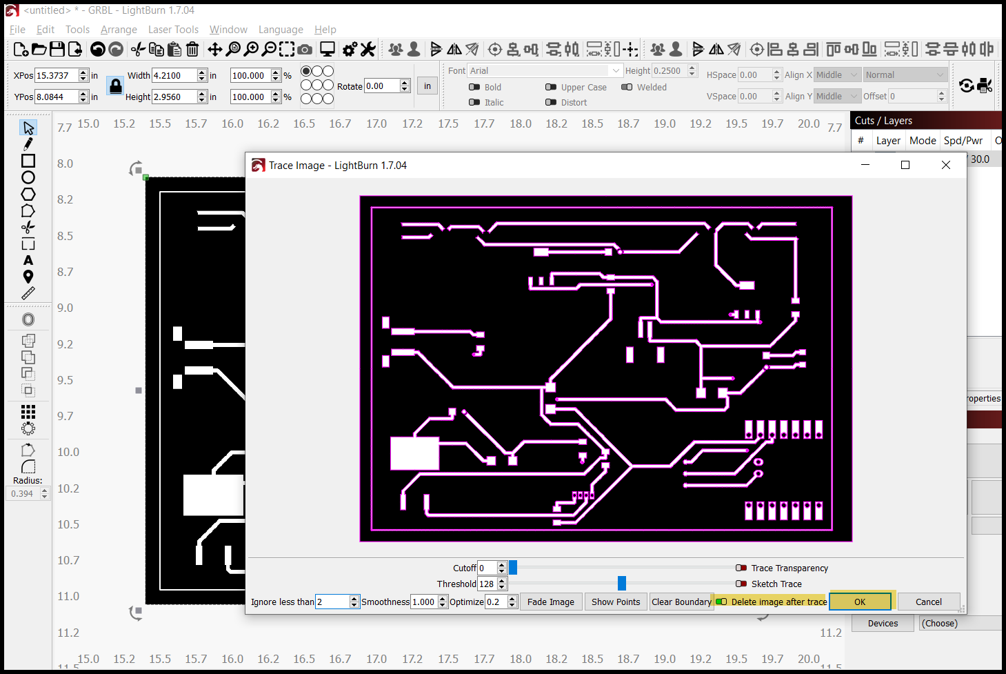
For yourself, the easiest would be to export a high res PNG file from Inkscape, import the PNG into Lightburn, and Tools>Trace Image. If you start with a high res PNG, Lightburn does a good job of tracing it.
I took a look at Cuttle and it looks pretty interesting, I set up a free account to try it and might be interested in purchasing.
Thanks
I’m a little disappointed. That’s the way I’ve “solved” the problem, but I think there should be a way to export the “entire” svg file so that it can be used directly in LB, after all it’s just a very simple line drawing. Where should it first go to a 3rd program?
1 Like
You are absolutely right, I was thinking the exact same thing.

This video may hold the key. ![]()
Though it can’t fix the stroke issue. As long as you can find a way to convert the stroke to paths in your circuit board software, you should be able to combine the shapes in LightBurn.
… This is probably where the problem lies, which @ednisley correctly describes.
I personally want to find me a PCB design program that gives me “free” options of export/import. I do not know Easyeda but do not like to be tied to a product this way (if it is as described).
I think the fundamental problem comes from the history of PCB design. The overall intent is to make a PCB and the “native” format for that operation was a set of Gerber files describing the geometry in a way suited to project patterns on photosensitive PCBs through a set of shaped apertures:
the plotter operator loads the paper tape with the Standard Gerber file on the plotter, manually sets the coordinate unit on the machine console and mounts the aperture wheel described in the accompanying wheel file.
As a result, the primitive shapes don’t form a “simple line drawing”, don’t have the connectivity required to extract one, and describe the geometry in a way that doesn’t fit into LightBurn’s basic assumptions.
Which is why the least-awful way to convert that geometry into something laserable is to get picture of the whole thing as a PNG, then either raster-scan as an image or trace to get the vector edges.
The backstory:
I still had to change the white perimeter in Inkscape to “stroke to path”. And, there were 2 white circles that I changed in Inkscape to “object to path”. Then Cuttle was able to flatten it correctly. I would still recommend exporting a hi-res PNG out of Inkscape, and tracing in Lightburn. For what you are doing, it will be accurate enough.
When you work with “free” programs, you accept their limitations. When I worked with a flexible circuit company in the early 80’s, their CAD program was 8K for 1 user. My company bought 1 seat, because it was easier to convert files using the same system.