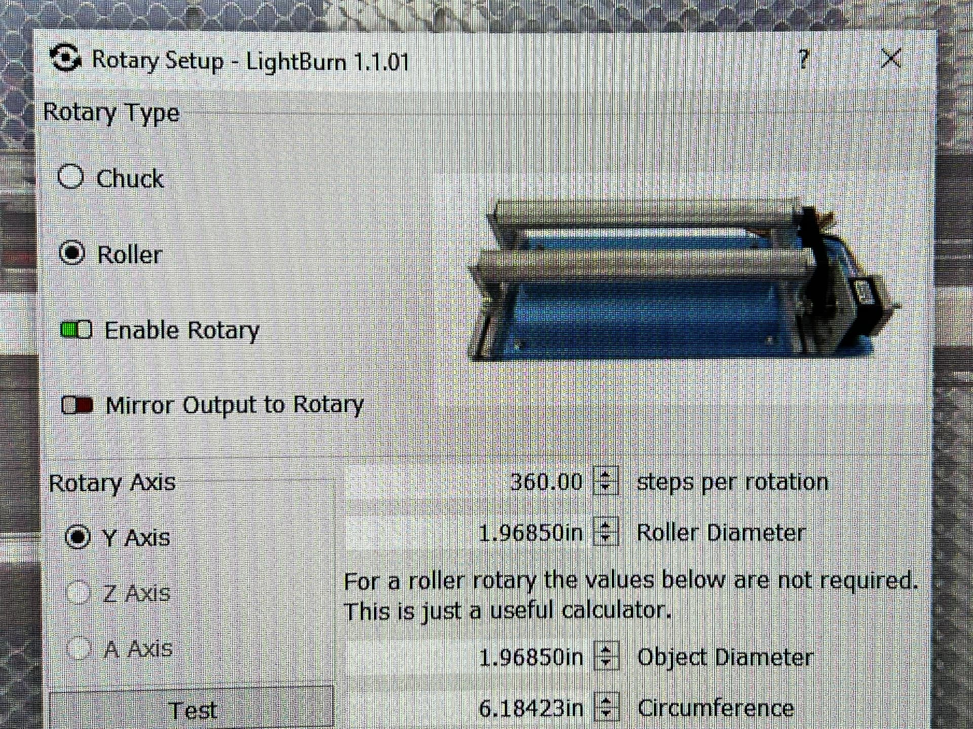
Can someone please tell me what I’m doing wrong? I’m trying to set up my rotary and no luck . It will spin completely during the test. But when I try to engrave an image on the glass this is what I get . I also added pics so you can see what I’m missing.

You might follow the thread I opened up yesterday in addition to anyone replying here. It looks like we’re having similar or maybe the same issue.
check the cables!!! I bought a OMTECH rotary and connect to my red and black laser. the cables are ordered for OMTECH lasers. If you have strange behavior when connecting, check the cables. I rearranged the wires in the connector and it works perfect for me now
1 Like
look at your driver controler in the Y axis what revolutions are setting, the double of that number is the right steps for rotation
but, first check the cables!!! nothing work without the right set
Where can I find the correct wire setup? Thanks
That is the problem, each laser had his own combination. Look behind the plug conector of the you Y axis, follow the line to the drive and write what line is A+, A-, B+ and B-. The trick is rewire the plug of the rotary to match with that combination.
Commonly in the rotary the cables color are ordered in that way: A+ (Black o yellow), A- (green), B+ (Red), B- (blue). Change the cables in the rotary plug to match with the order in your laser. (Don’t change your laser plug or your Y axis stop working). You know that is right when in the test of Lightburn the rotary spin a one whole 360 and back to the origin point. When that is ok is necesary change another thing in your machine settings but first do that and contact me.
I too have had all sorts of problems figuring out my chuck type rotary and getting it to work properly. I see you have a setting of 360 steps per revolution which sounds really low. Check what your stepper motors are actually set for - there are some DIP switches (I think that’s what they’re called) on the controller and a chart to tell the steps of the motor that correspond to the switch setting. I’m guessing it will be in the 1,000’s, not 360. Once I set this setting to 59,000 (or something close to that, I don’t have it currently installed to check), it’s worked perfectly. Try changing the 360 to 2000 and see if it’s closer to what you want or check the DIP switch and put in the actual number.
Thanks I will definitely try it. Thanks
Thanks will do
yeah almost all steppers are 200 steps/rev (there are a few 400). Then the drive may be 10x microsteps per fullstep. Then, there’s probably a reduction ratio (count the pulley teeth).
200*microstepPerFullstep*reductionRatio
360 isn’'t right.
Your numbers in the configuration do not look correct. You need to look at your motor driver to tell how many step/rotation it’s configured.
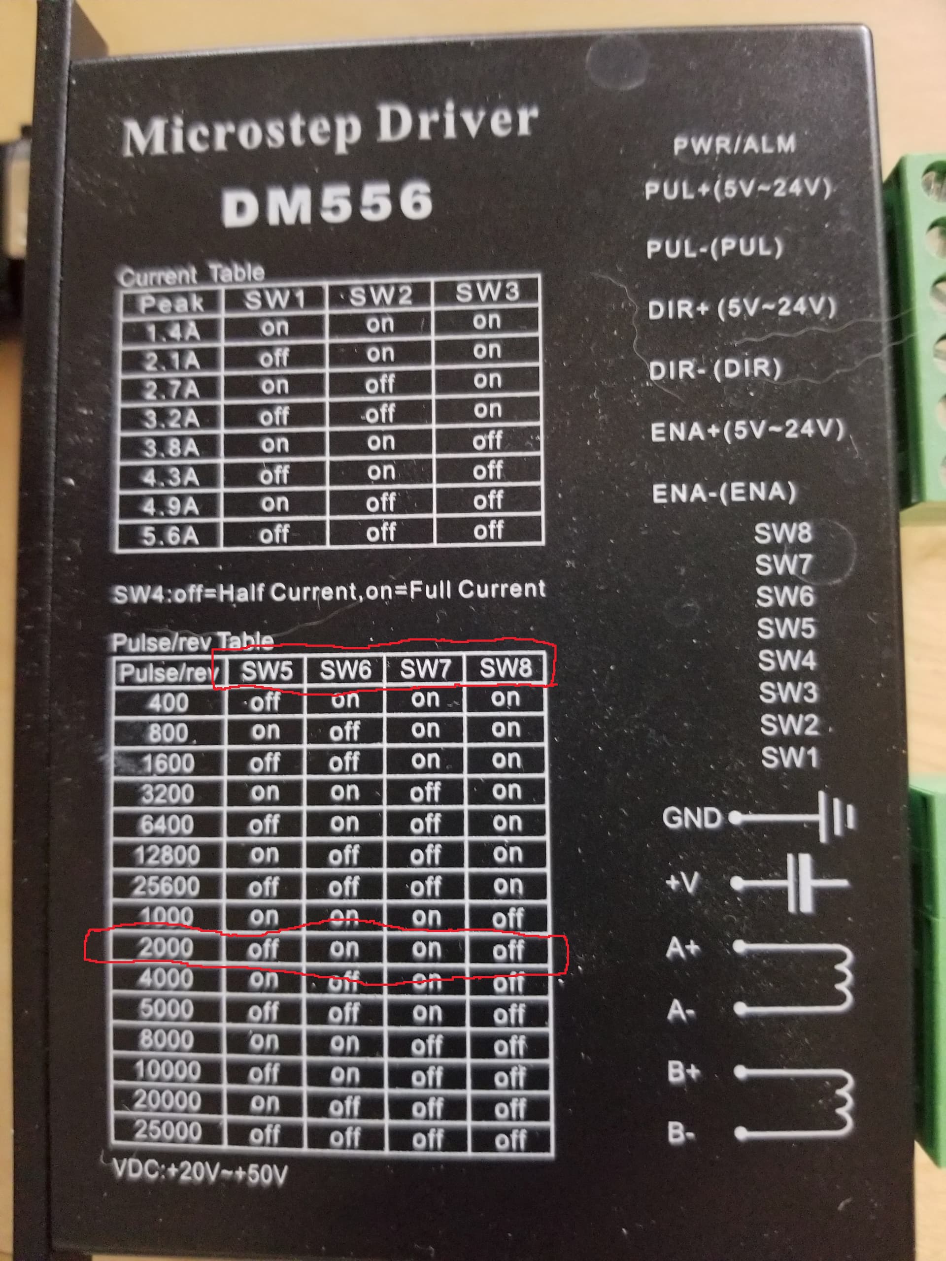
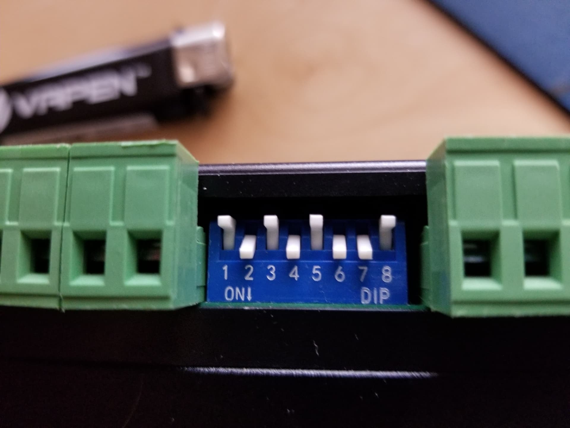
mine is set for 2000 steps/rotation.
Then you apply the ‘gear ratio’ to the wheel to get steps/rotation for the rotary.
In my case, 2000 (motor driver steps/rotation) x 2.5 (‘gear ratio’) = 5000 steps/rotation that I enter in the rotary menu for ‘steps per rotation’
You are telling the machine how many steps to move your ‘wheel’ or ‘roller’ 1 rotation.
The only other information needed would be the ‘wheel’ or ‘roller’ diameter.
Mine was suggested at 64, but 63 was perfect. The results should be very close…
Good luck
![]()
Right, I didn’t notice you were using a traction-type tire rotary.
Those are common, and kind of awful. Find a chuck type rotary that fits your jobs and you’ll never touch those again.
The traction ones don’t have a really determinate reduction, as it depends on tire diameter, and they do slip as they go, which becomes readily apparent if you’re using it for back-and-forth vector rotation. A chuck type is a determinate reduction ration and absolute repeatability as it rotates back and forth
A wine glass, something tapered, or a 64 oz with a handle… in a chuck rotary…?
Not that it’s impossible, but a thin glass that’s odd shaped has virtually no where to ‘chuck’ it, if tapered you have to shim up the end of the machine… It would have to be huge to handle a large mug…
I have a different configuration for the same rotary depending if I’m doing vector or scan work.
You really have to slow down the axes in acceleration, max speed along with the start speed for Ruida.
You need to really pay attention to what kind of max speeds you’re expecting to use if you are vector cut/engraving.
Each type has it’s pros and cons.
![]()
Yep! Check this out:

Point being, it’s mounted axially, and the interface is static in that it just grips with no relative motion. I’m not saying the centering of the wine glass would have zero error, but a 0.1 deg rotation command always yields 0.1 deg rotation along the mount’s axis and if you rotate 360 back and forth 10 times you will have no cumulative error whatsoever regardless of speed or accel.
A traction type is based on a rolling interface with tires. Note the location of the actual work axis is going to vary with radius of the work you put on it. Say a wine glass is not a perfect circle- nothing is “perfect”- and is slightly oval. It is 75mm dia in one direction and 77mm in another. If mounted on an axial chuck, this creates a 1mm variation. On a traction roller, 2mm variation.
The traction roller’s tire interface is just a roller. It’s not all that exact, and there is always some “slip” error so back-and-forth motion for vectors may have unacceptable error. And speed/accel becomes very important as the work can slip.
Traction rollers only hold by gravity, so off-center weight can be a problem. And mugs with handles can’t engrave the opposite side of the handle since the handle can’t feed across the roller.
This topic was automatically closed 30 days after the last reply. New replies are no longer allowed.