Can't get limit switches to reverse polarity

Hello,

I’m replacing my old lasersaur board with a ruida RDC6445GT5 controller and have an issue with the X and Y limit switches. They all worked well before and each only has two wires for which the polarity is irrelevant, so I’m pretty sure they are wired correctly. The issue is that all 4 limit switches are always recognized as “on” (the LED for the switch is lit up) when the laser head is in the middle of the laser. The switches are NC, here’s the original wiring diagram: (wiring · nortd/lasersaur Wiki · GitHub). If I manually trigger one of the switches, the LED turns off. The rest of the homing behavior works correctly if I fake the switches to be inverted.

I tried changing the limit polarity in the ruida controller vendor settings, but it seems to have changed nothing. Would it be better to change it via lightburn?

Any tips would be greatly appreciated!

Why do you have 4 switches?

To home on 2d only requires 2 switches.


The Ruida has inputs for both home and limit switches. Your reference limit switches, but you speak about them as home switches…

Since about no one uses limits on a Ruida, the terms have become interchangeable… Probably because grbl uses them for both.

I would assume you are trying to get the machine to home… I’d start by disconnect the pair of switches that you don’t need…


How do you have them wired?

This is mine, notice that the Y limit goes to LmtY- not the LmtY+ which is the limit input. AND where is the ‘other’ side of the switch wired, ground or 5V?


The Ruida generally uses NO switches and pulls the input low for active. So you should have to invert the home input in the Ruida.

Here is the layout for both home (red) and limit (green) switches…

Good luck

:smile_cat:

Thanks for the picture, that already helps! Wasn’t sure if home was - or +, I think I have those inverted actually. I have 4 identical switches, the setup is exactly the same as yours where there’s one switch on every side and I have connected them to ground on the Ruida. The 5v is empty, I tried switching the wires from ground to that one but then they just become entirely unresponsive.

If I switch the polarity of the limit switch on the Ruida controller, would this not mean that all 4 limit/home lights should immediately change status to their opposite?

You were not clear on how they are connected…

Since they are NC switches are they series or parallel wired?

NC I think would need to be series wired since they are both ‘conducting’ all the time. The Ruida can’t use 2 of these switches.

You don’t have enough switches for home and limit. Once the Ruida homes, it no longer looks at home switches, just limit.

If you want to simplify debugging this thing… remove the wiring of the two useless switches.


  1. remove wires to extraneous switches, just disconnect the wires.
  2. one side of switch goes to 5V to pull up the Ruida input when it’s not active.
  3. invert the home within the controller

Make sense?

:smile_cat:

The markings are … ambiguous.

The LmtX- and LmtX+ terminals correspond to the left and right travel limits, not the signal polarity. Similarly for the Y and Z / U axes.

So if you want it to home at the front right, you’d connect the front Y axis switch to LmtY- and the right X switch to LmtX+. The other side of the switches goes to ground, because the terminals have internal pullups.

The 6445G manual shows “Limiter” settings in section 8.5.2, which may be more easily accessible through the LightBurn Vendor settings.

I think:

  • Limiter polarity would be positive for NC switches
  • Enable limit trigger (triggle?) enables the switches
  • Enable home does what it says

I’d leave homing disabled until I sorted out the various enables and polarities, but I’m just cautious that way … :scream:

Considering the Chinese wrote these most of what they say isn’t very clear… They don’t really explain this… I learned it by trying it…

This is absolutely incorrect. Check post 2 with a diagram.

Home are the - inputs… Limit uses the + inputs.


The home switches are never checked once it has completed a home. Only the limit inputs (+) are active after a home.

You can go in there an pull them to ground …


Don’t do this either …

Also he doesn’t have enough switches for a home and limit operations, takes a minimum of 6.


Switching around which quadrant it’s using sounds easy … many people who have tried it may beg to differ with it actually being ‘easy’ …

:smile_cat:

Ok, so forgetting about limits for a while, I unplugged the two “end of the line” switches and only left the two for homing. Above diagram is how I had them connected, like this they are always on until they reach an end and then they turn off, which is the inverse of what should happen.

On your recommendation I switched the ground wire to 5v, but then they simply do nothing no matter what settings I change. Did I misunderstand that?

Thanks again for the help, really appreciated!

If the head moves the right direction during the home operation, this should be pretty simple…

Did you invert the home switch in the controller…?

Make sure the controller know the home switch input is inverted.

I think what it’s looking at is that when it’s not active (or being pressed) the signal will be pulled low by the NC switch. When activated, the input pin will go high signalling the controller…

I think you have it wired right, but if you are sure you’re setup with the controller and such, these inputs are pretty tolerant and moving the ground to 5V shouldn’t hurt it. I think that’s the pin on the other end of CN4… (I think it’s power for x and y limits).

Got to bake some stuff … I’ll check back now and then…

Thanks for the schematic …

Good luck

:smile_cat:

The head moves in the right direction if I disable the limits, otherwise it thinks it’s at home everywhere and does the slow backing away from the home switches (indefinitely).

I’ve been testing every combination with the “limit polarity” in above image, assuming that’s the home switch polarity you mean? When connected to Ground like in the diagram it works but inverted (and this limit polarity setting changes nothing), when connected to Puxy it never shows as active no matter what I do. I should mention they are magnet switches, not mechanical, although that shouldn’t really make a difference I guess.

Are they inductive like this?

Yours might say PNP instead of NPN.

Or are they a magnetic reed type?

:smile_cat:

Which suggests the switch polarity is inverted. The default seems to be Normally Open switches that close on activation, so the input is pulled high when the switch is not triggered. The polarity is set to Negative (or some such) to invert that and make the input active when the input is switched low.

Section (9.1) of the 6445G manual seems relevant:

Direction Polarity: Modification of direction polarity can move the motor to the opposite direction. The modification purpose can move this axle to the origin on resetting. If this axle moves far from the origin on resetting, it means the direction polarity of this axle is wrong in setting and should be modified.

Spacing Polarity: it is used to set the high and low level mode of spacing signal. When the motion axle arrives at the spacing position and input a low-level signal to the mainboard, the spacing polarity at this time should be set to be minus.

The first one lets you pick the direction of homing and the second sets the switch polarity when it arrives.

Because the homing direction is (apparently) configurable, it is unclear (to me, anyhow) whether the + and ’ input terminals would also interchange.

It is exceedingly unclear whether the homing direction also influences the coordinate axis direction. I think it does not, but can see the possibility of having the positive and negative coordinate directions flipping in amusing ways.

Proceed carefully!

They are reed switches, exactly these:
https://www.mouser.be/ProductDetail/MEDER-electronic-Standex/MK04-1B90C-500W?qs=8xMK%252BwDsXhcQnbOO7Xd2kA%3D%3D

1 Like

I don’t think you want lmt enabled as that’s the limits not the home.


I’d suggest you use Lightburn via ‘Edit → Machine Settings → Vendor settings’ and make your modifications there… while you are there make a backup copy in case you break something. Don’t forget to ‘write’ it back to the controller after you make a change.

Lightburn has specified what some of these do in their guide. Don’t have to deal with the Chinese translation problem.

When ‘home’ is enable it will attempt to home, this enables the ‘home’ switches.


According to Lightburn documentation “(limiter polarity) tells the controller whether the limit switch triggers high (normally open) or low (normally closed) when contacted”.


One of the big issues here is that we commonly use limit switch/home switch as the same animal… Ruida calls them limit switches in most cases, but there is a distinct difference and you can see the confusion.

For instance, how would you invert the actual limit switch inputs, if you had them?


Here’s a copy of my Ruida for the X axes… they are pretty much all the same for each axes. Home is enabled but limiter polarity and limit trigger are not. I use nc switches as the machine expect.

Thanks for the reed switch link… assume you know they are NC type?
When I used these there wasn’t an option as the magnet cause the reed to make contact… Wonder how they do NC with reed type…? Another chunk of Ferris metal…

Assume you have a volt/ohm meter?

:smile_cat:

There being nothing quite like a good new problem to take one’s mind off all one’s older problems, I just did some tinkering with the X axis settings…

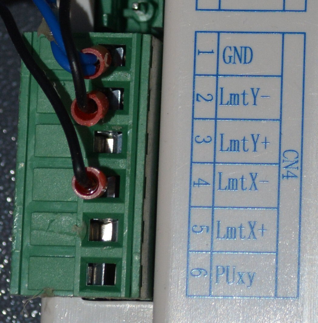
This is on a Ruida-ish KT332N, but the manual’s verbiage is pretty much the same as the 6445G.

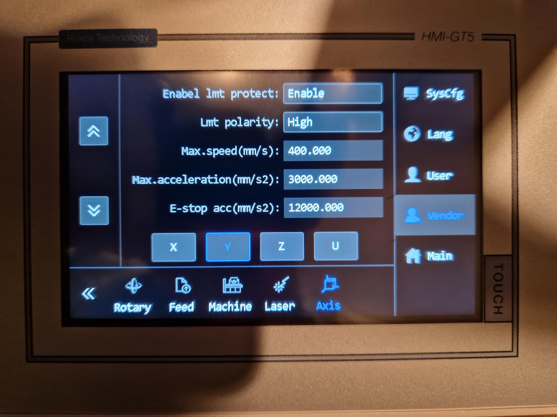
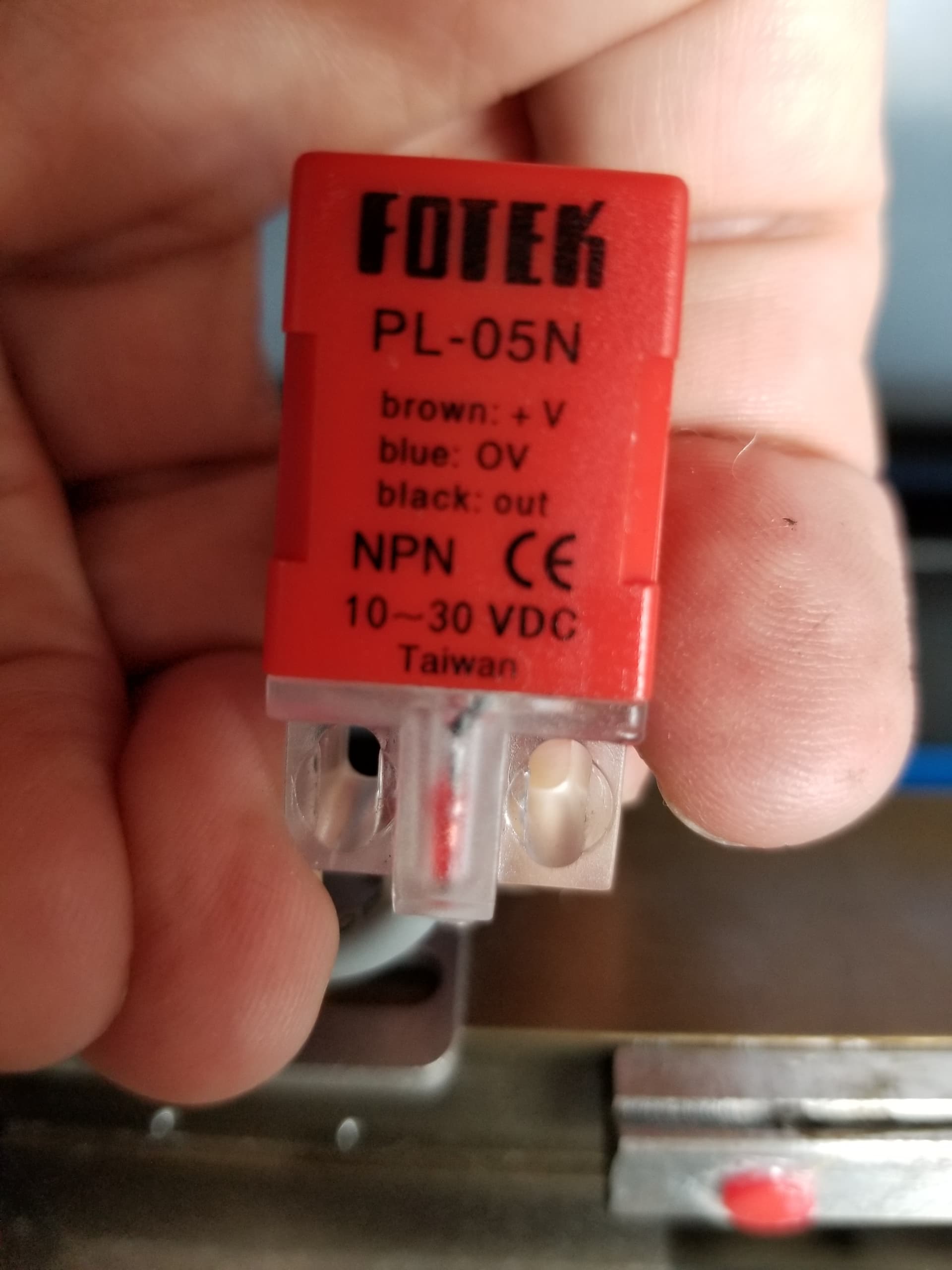
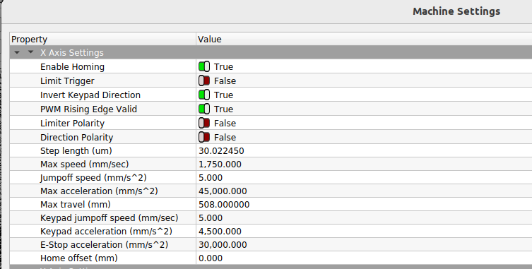
LimIter Polarity inverts the sense of the limit switch input signal. My OMTech has Normally Open proximity sensor switches, so the default setting of False makes it inactive in the middle of the platform.

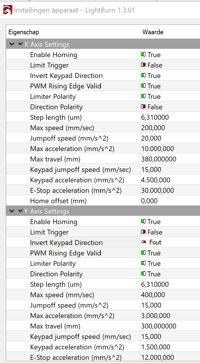
I set it to True, which made it active in the middle of the platform.

So True would be the correct setting for a Normally Closed switch.

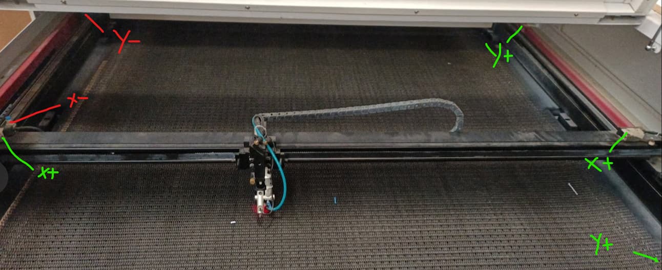
Direction polarity sets the direction the axis moves during reset, which must be toward the home switch. Mine was set to False and it homes toward the right side where the limit switch sits.

I set it to True and it started homing toward the left, where the limit switch isn’t. Hitting Esc on the control panel stopped the homing process and left the head in the middle of its travel, unhomed.

Apparently Direction Polarity directly controls the DIR signal to the stepper motors, because both the control panel keys and LightBurn’s motion buttons then moved “the wrong way”.

That does not affect LB’s machine coordinate origin, which remains at the top right of the layout, or the orientation of the X axis, with values increasing toward the left as usual.

The Invert keypad direction setting inverts the motion direction with respect to the homing motion. Mine was False, but flipping it to True reverses both the keypad and LB directions.

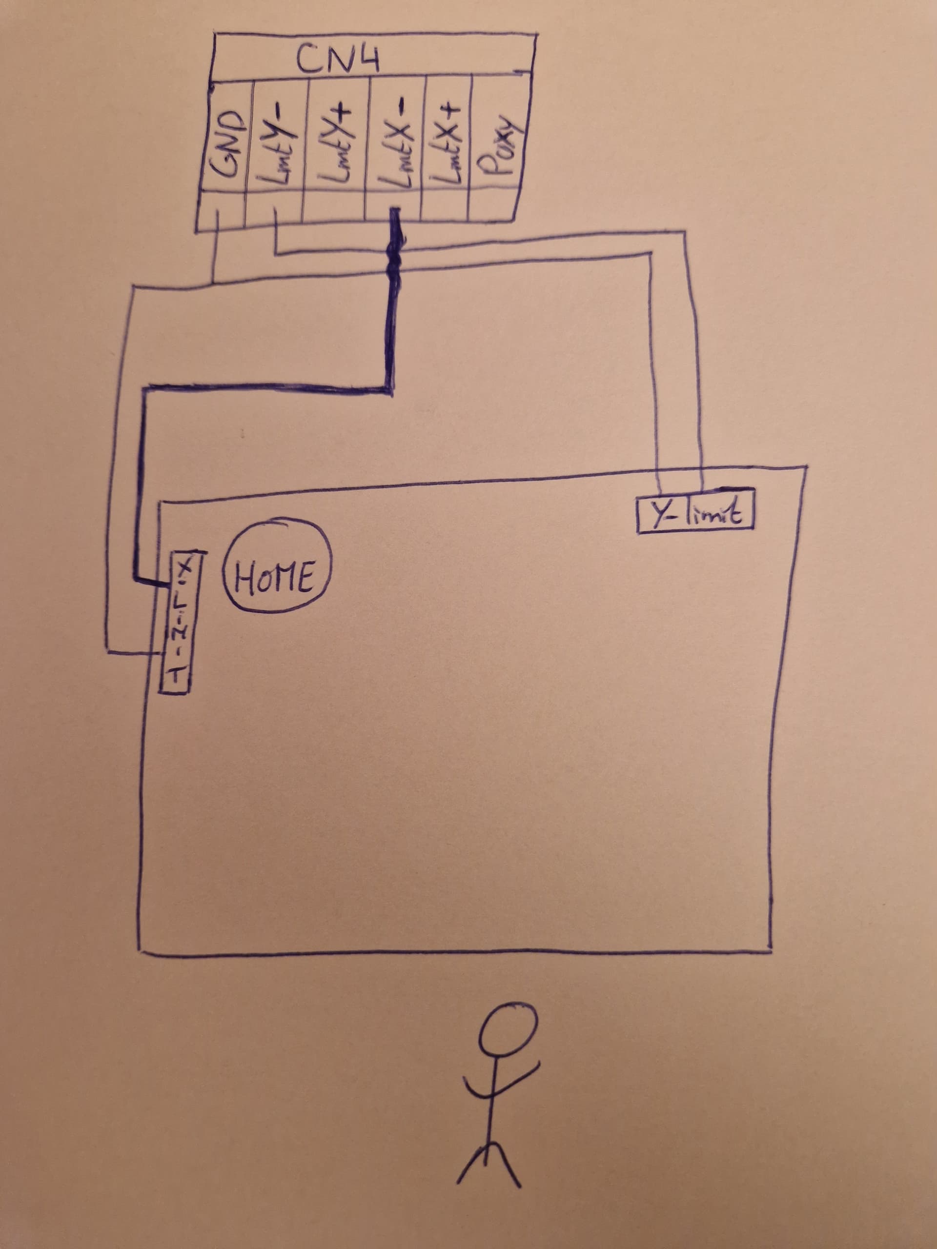
I think Limit Trigger refers to “hard limits”, which requires a limit switch at each end of the axis, but my controller does not have the + inputs that would allow me to test that. The controller doc says it uses “soft limits” to prevent out-of-bounds motion by using the home position and maximum axis travel value.

So the available options allow all possible combinations:

  • NC or NO limit / home switches
  • Homing direction
  • Keypad / LB motion commands

Changing those settings requires a controller reset, which will trigger a homing operation if it’s enabled.

Admittedly, the nomenclature leaves a lot to be desired, but their English is far better than my (nonexistent) Mandarin.

With that in mind, careful experimentation on the actual controller in hand seems prudent …

Hallelujah, it’s been fixed. Thanks immensely both of you!

The solution was a combination of a few things:

  • The setup where they are connected to ground and not 5v as in my stick figure diagram worked
  • Homing was originally disabled (because it was breaking the machine in the wrong setup) - I had assumed that the limit switches would act as both limit and homing switches which is not the case, homing needs to be enabled and from that point the controller remembers that position as the limit. My old controller did not remember this… I tested with a lower homing speed.
  • For some reason still unknown to me, the settings for X and Y axis are different, but following ednisley’s explanation I was able to work out the directions. Inverting the polarity of the limit switches also inverts the homing direction for some reason? Mysterious.

In the end I’m still not quite sure why this works (and confused that the LED and IO reading on the Ruida controller don’t change at all even when the setting and resulting action do) but ok, here’s my final settings:

I believe you can change both invert keypad direction and direction polarity and have the same thing… Some of these behave that way… of course it may affect other actions.

If it’s working I would have fun with it, not try to break it again :face_with_spiral_eyes:

This shouldn’t happen… They are entirely different from each other…


Very glad you’re up and running.

Now post some of your wonderful laser work :+1:

Take care

:smile_cat:

I can for manual operations and lasering, but then it homes in the other direction :face_with_raised_eyebrow:

I’ve previously posted some of my projects on instructables with a step by step and files, if you want to make one :slight_smile:

This topic was automatically closed 30 days after the last reply. New replies are no longer allowed.