After hassling with the Y-axis issue, I went back out to the shop to start up again.
Noticing that it wasn’t cutting 1/8" acrylic at 100% power, just etching. 4 passes later, nothing; also noticing that the cuts weren’t even in depth, from one end to the other.
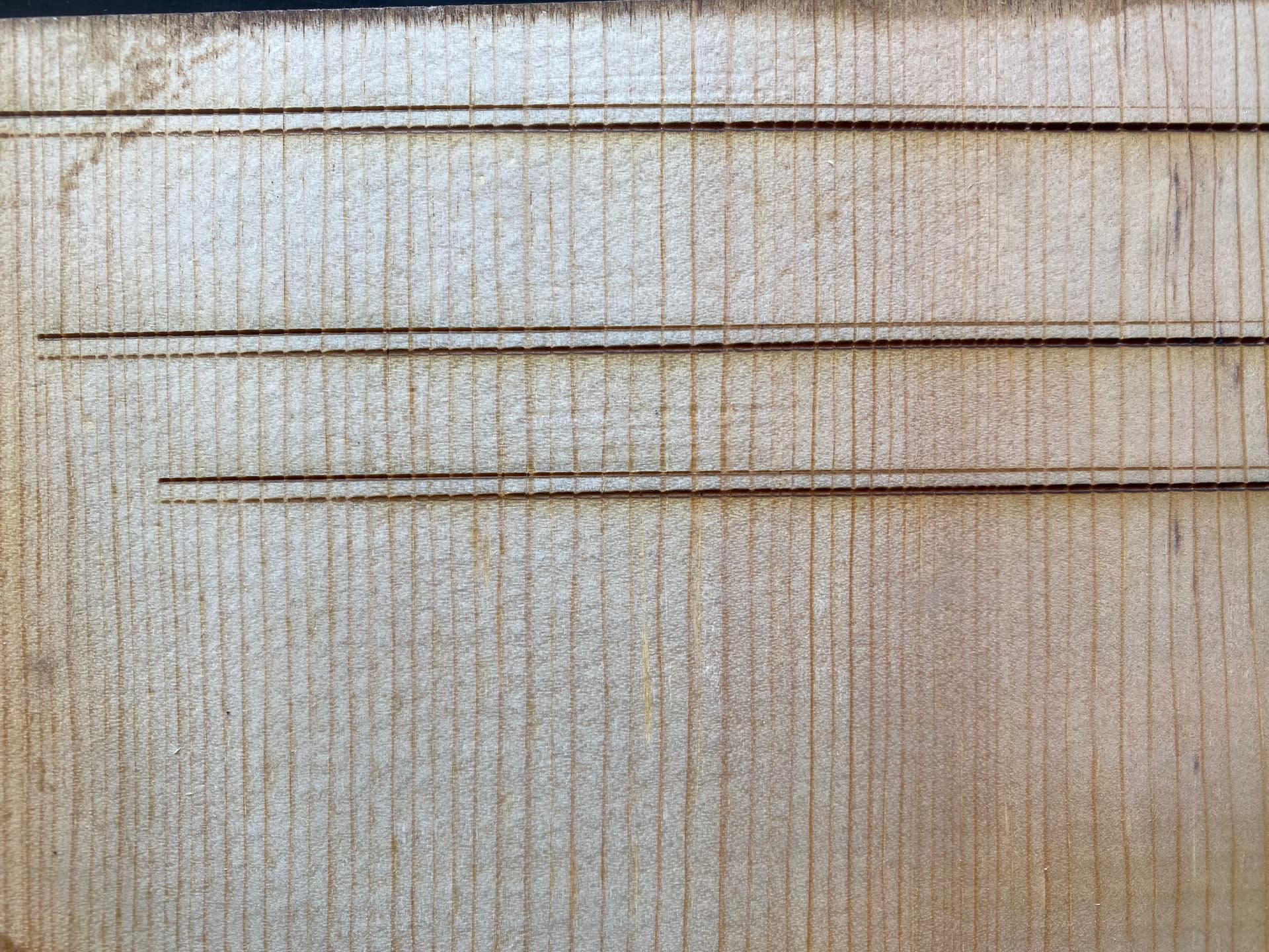
Did a focus line test, and got this…
X-axis only. Goes about 5 inches like this. Like the laser is in two different places at once, and at two different intensities.
Anyone seen this? Is this gantry, or alignment between mirror 2 and 3? Or…?
To rule those out, a thorough check of the beam path is in order.
The nightmare scenario, though, is a tube failure, where it is no longer resonating in TEM00 mode. While you’re checking the beam alignment, take a close look at the beam shape at Mirror 1: if it’s not a nice round disk, that’s a Bad Sign™. This discussion covers the details:
This made me reflect on today’s experiences and remember that there was a moment the Y axis decided to do its own thing, resulting in a smacking of the nozzle assembly against the gantry base frame.
Messing around with it, and I’ve gotten it much better…sorta.
Look at this font and how messed up it is…(bottom one…)
Yeah… while I was having dinner, I reasoned that there was a difference between the tension on the X belt and Y belts.
Just got back in from making changes and doing more tests. Getting REALLY close.
Tested cutting some letters on that same piece of frosted green; the first four came out, the fifth one started to cut clear through, and the last three were still not cut all the way through.
I did another line test for depth, on a piece of wood. It would seem that on longer lines, I still have the reflection issue. It just takes further down a path, to show itself, and it’s pretty evenly split, half and half, this time. The line(s) are thinner and separated in the middle, now, as opposed to a few inches from the end. It appears that as the mirror moves towards the center of the rail, the issues starts up and then fades away as it keeps moving down the rail.
The mirrors’ not cracked. I’ve been trying with the mirror adjustments, and adjusting the mount (to the X gantry rail) itself. Until I can get one of those laser units that feeds from the nozzle end, I’m probably just chasing my tail.
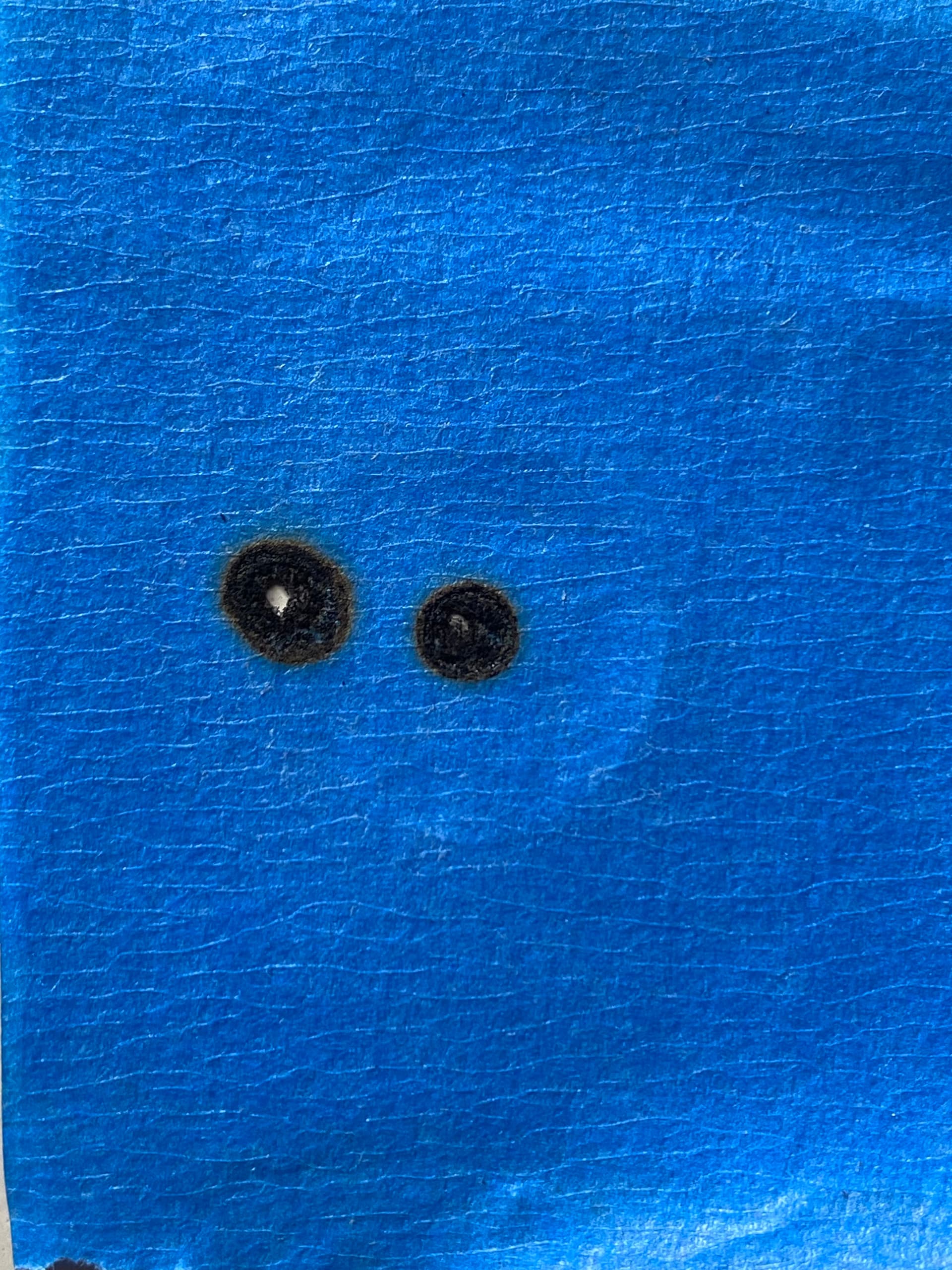
Earlier, before dinner, I did some tape tests. Blue tape is really flammable, geez.
I haven’t figured out how to pulse the unit, yet, so I made a test file, and would stop the file almost immediately after it started. From what I can tell it looks like the beam from #2 is hitting #3 pretty much dead-on, but I need to find some tape that doesn’t catch fire so rapidly.
OK. So… this is the pulse test.
The center one is the result at top left and bottom left; the one on the left, is top right and bottom right. The results on each side are identical from top to bottom. It drifts that far during X axis travel.
I’ve done some cutting tests and it really seems that everything starts to go south, about halfway across the table; I can produce all sorts of nice, clean cuts on small pieces if I keep everything to the left side of the table up to the middle.
Noteworthy is that as the cutting progresses from left to right, the depth of the cut gets shallower; I tried cutting a long piece, with 7 instances of the same item in one line from left to right and only the first one on the left was complete…the next few were close but got progressively lighter by the end.
It seems to me, to be a bit extreme for a simple mirror misalignment…like something else - bigger - is out of whack but for the life of me I can’t see it.
The point is, is it normal for the other end to be identical in misalignment? It seems a little too coincidental…like the mirror is aligned but something else is causing it to drift evenly.
It’s not all that unusual. It appears that there is a slight difference in the 2 burns at the far side. Just adjust them a little bit at a time until they align.
Sure! Mirror 2 is aiming the beam slightly to the rear of where it should be, so take another pass at it. You’ve done a good job so far and a little more tweakage will get it done.
FWIW, having the beam far enough off-center to hit the edge of the aperture at Mirror 3 will give you exactly the double-beam effect shown at the top, because the beam will almost certainly be splashing off the edge of something between M3 and the nozzle orifice.
Went back out to finish the dial-in… getting SO close, then the controller starts acting up. Display flickering, then going to black. Can only get it to do something after a reboot, and then I only get a couple minutes before it either goes black, or does a restart. Basically, I have to wait until lit decides it’s gonna behave, then try and mad scramble to get some pulses in and make adjustments before it blanks/restarts again.
I can’t tell you how close I got on the last pass, but when it blanked out again, I’m surprised the entire forum couldn’t hear my cussing.
Now I have a controller that seems to be dying/dead. Just what I need… to spend more money I don’t have, which is what I was hoping to remedy with this laser.
I live on an hill, and three lots down from me is a gulch. The laser is sitting on a wheeled cart I built.
The inclination is growing.
It occurred to me, yesterday, that I could use scrap acrylic to accomplish this… make an 18mm disc, that can stick on the back of tape, and fill the hole.
Yours may also supply 5 V, which means you’ll need a dual-output supply. I’d be tempted to measure the 5 V current, because it likely handles only a red-dot pointer and maybe a couple of switches, then hack in a wall wart.
Well, I spent a little time yesterday on the PS. There’s a trimpot on the output side, right next to the 5v terminals…you know how trimpots can get a little non-cooperative, after they’ve sat in one position for a long time? I think that was the case; I rotated it a little, back and forth, and got it to stabilize at 24.5v-ish. I intend to spritz it with DeOxit, just for good measure.
I don’t know what the ratings are on mine, though. (Haven’t taken it out to look.) I like your suggestion of getting more power than is needed. When I used to rebuild power sections of some pieces of gear, I’d purposefully replace caps with ones rated for much higher voltage, so they weren’t running at 90% capacity all the time.
Yeah I do have a red pointer at the nozzle. Sucks that I’d have to add a wall wart somewhere for that… you’d think I’d be able to find a 5v rail SOMEwhere in this machine without having to resort to that.
Depending on which controller you have (and I know enough about K40-flavor lasers to realize I know nothing about their myriad controller possibilities), it may have a +5 V output you can vampire for low-current widgetry.
My KT332N has them on the stepper output terminal blocks:
Add up the “peak current” selected by the DIP switches on all the stepper drivers, add an amp for the controller, add any solenoid valves, then add anything else connected to the supply. Compare to the supply’s current rating on the sticker cleverly placed where you cannot read it without unscrewing the supply from the machine frame.
Do not roll your eyes.
I have a little bottle of DeoxIT (I think they screwed up the capitalization, too) Red that looks to become a cherished heirloom passed down through the generations: the tiniest drop solves many problems!