Can't win, today: Now, it's alignment

Oh, I didn’t roll my eyes.
I did, however exclaim loud enough for my neighbors to possibly hear… “6 AMPS!!! AYFKM!!! SERIOUSLY!!!”

The PS isn’t trustworthy at the moment… my Fluke kept jumping between 12v and 24, while simply sitting there. I finally got it to behave but who knows for how long.

six. amps.

It does, however, have a 5v terminal on it.

OK so now I’m back to considering getting this thing going at a good clip in my alley and letting it careen off into the dry gulch at the end of my street.
It won’t cut 1/8 acrylic even with several passes.
Finally decided to start looking all the way back, at mirror 1.

As you can see, it’s hitting M1 at a little bit NW of center (enters and exits M2 at the same location). There seems to be no way to adjust the entire assembly, to correct this. So does this mean that M1 is to be adjusted so that the beam hits M2 in center? That M1 is responsible for correcting the beam output at the tube?

I know this doesn’t help your issue, but your issues confirm what I’m about to say.

When I was researching which laser to buy one of the youtubers commented to avoid a K40. He said they got that name because you will want to kill yourself 40 times over trying to make it work right.

This was given to me, by a guy on Facebook Marketplace, who had upgraded his shop to an Epilog.

The price was right. You can afford to put a little time and money into it.

To make sense out of the mark at m1, you need to use as little power and duration to check the mode of the tube.

:smiley_cat:

well at the moment I most concerned about getting the beam to hit center of M1, going in; this was the basis of my question about M1 being tasked with correcting the alignment, further down.

I’d venture to say the tube isn’t seated in it’s holder. That’s about how much they are off if they don’t seat properly.

What kind of adjustments do you have on your tube mounts?

:smiley_cat:

Basically. none.

Now I’ve got another issue: “Frame slop”. Keeps telling me it’s there, but I can’t get around it and I have no idea why it’s giving me this message.

You usually get this if the code is attempting to drive the head out of the working area.


  1. Where does the machine home?
    a. what is the origin in the device settings?
  2. What is the start from mode?
  3. What is the job origin?

Do you mind posting the lbrn2 file?

:smiley_cat:

Echoing the checks, also check that you haven’t moved something or something has come loose. Everything must be parallel or your mirrors will not align.

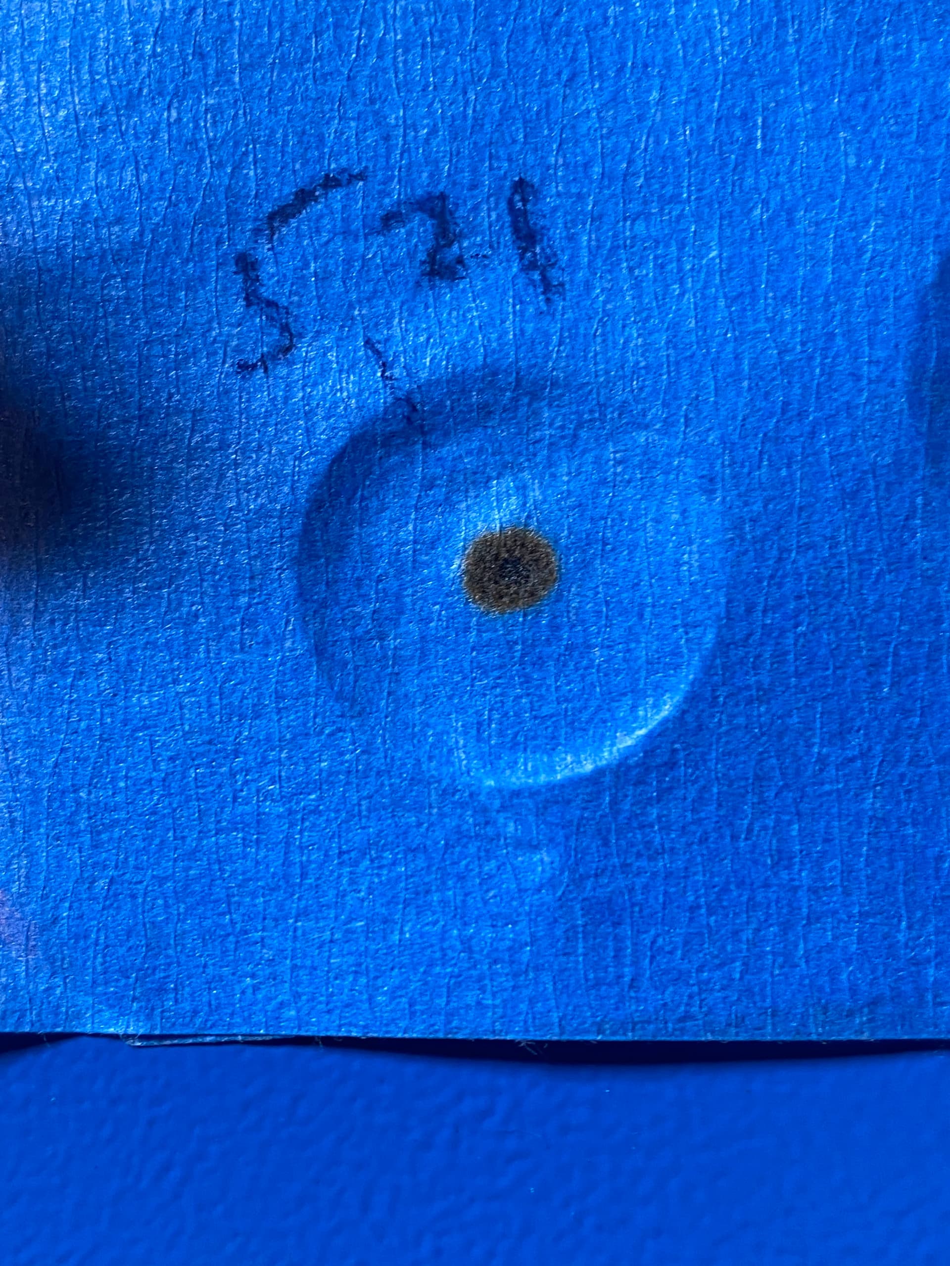
All of the beam energy has to land across M1’s exposed mirror surface. It can tolerate being a little off. But some of the beam energy is outside the diameter that is intense enough to burn tape, you don’t want to waste it. This may already be capturing it all, though

So, it’s a little high. Being forward also means when the beam comes down the Y on the left (rear to front), it will be a little further to the left.

In a system done with loose tolerances, you need to look at the whole system. If it’s hitting M2 dead center as far as left-right is concerned when M2 is at either limit, then M1 is aligned but offset a bit. If you just move M1 to the front of the machine to get it centered better on M1, it will not be on center on M2 anymore and you might have to change the mounting offset of M2.

That’s if you were to move M1 to the front of the machine. If instead you just shift it to the left, that will get the beam centered on M1 without offsetting where the beam goes down the Y.

Thus aligning it first and seeing what offsets might be needed second is a sound strategy. It’s not the only strategy.

The z height being high, you actually do need the system aligned first. Because the overall XY plane of the gantry “is what it is”. If you pulled up all the gantry rails and put a shim washer under each one, sure, you could offset it upwards, but we don’t do that. The Z height of the XY plane is already determined by placement of M3 and M2. Think in reverse, it’s equally true- if the beam starts at the lens, hits the center of M3, M3 is angled to hit M2 dead center, then M2 can only be adjusted to be parallel with the Y rail as it goes back to M1. Anything else would be wrong. If it hits M1 too high, that’s the prob. Nothing about the angle of M2 or M3 affects that. Offsetting the mirror locations would, but we’re not going to do that.

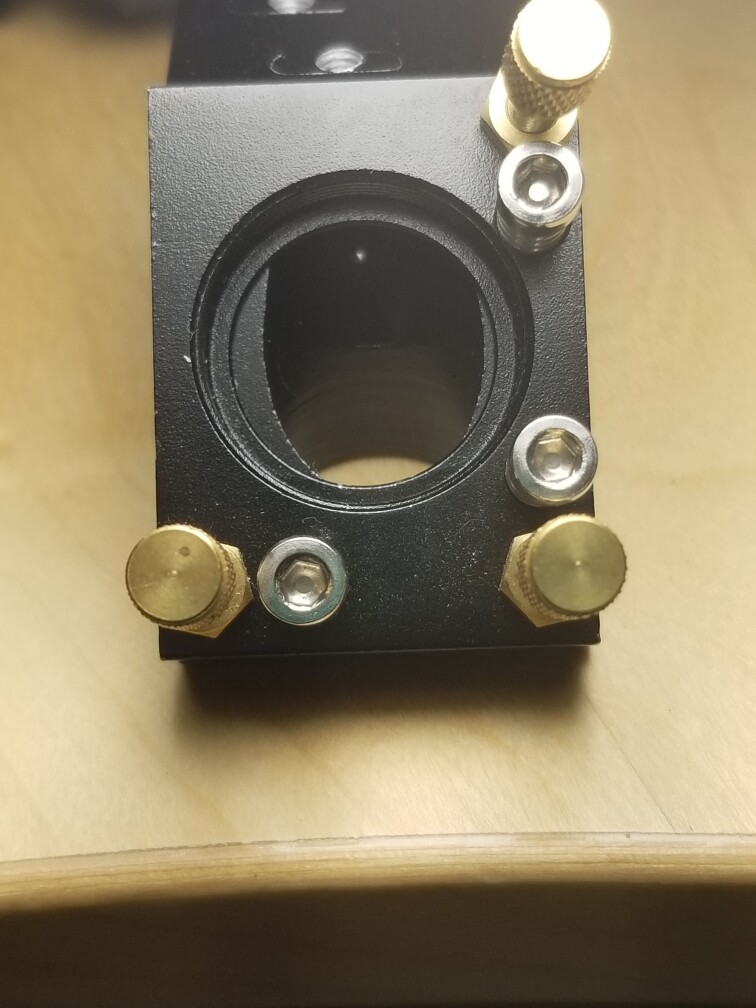
This is probably not an M1 angle issue, or any mirror- the tube is off. Tube mounts usually have Z lift screws and a locking screw. Undo the lock screw and move both down, or only the one closest to the mirror lower or only the further one higher. The second two options change the angle of the beam before it hits M1. M1 can be aligned all the same to get the beam dead center on M2, it won’t care.

Generally speaking you want the tube “level” of course. If you find the tube isn’t level to begin with and one of those single-mount adjustments gets it centered on M1 while lessening the angle, you’d of course favor that one. “Level” can be subjective though- generally speaking we’d be defining it as equal height of the two mounts to the horizontal sheet metal they’re attached to. But that sheet metal itself may be “off”. Doesn’t matter that much which way you go, though.

Or, well, it CAN be that the tube is already coplanar with the gantry xy plane and M1 alone is simply mounted low. On some mounts the whole combiner assembly is on a rod fixed with set screws and it can be moved up and down a small amount Low can also be compensated by putting washers under the mount, but some I’d have a high threshold of evidence that the mirror’s location is the issue, but it does happen.

AH. Got it. That is what I was inadvertently attempting to do; it was a file with nothing but a straight line, just for testing purposes, and I was asking it to extend beyond.

Still battling the alignment. Had it spot on yesterday, but still no luck.
I did another cut test. Small graphic, 10mm/Sec, 100% power, 2-pass, 1/8" acrylic. Did not cut all the way through. Didn’t even touch the backing paper.


Lots of pulse tests help me see that the beam is not coming out of the nozzle, directly underneath… seems to be offset a bit.
This doesn’t illustrate it as neatly as I’m seeing it, but it’s close.

This is like punching a bean bag.

While I was fussing with this, other thoughts wandered into my head…like, what if it’s a bad tube (that would work just fine last week and now, not); a replacement tube runs around $150 and with a newer power supply I could probably freshen up my existing wattage for about $200.
Assuming physical tube length can be accommodated, and upgrading the power supply, would it be possible to bring this thing up to 60w?

Should’ve left it alone when it was on… :face_with_spiral_eyes:

This can be the head not being square to the table or that the beam entering m3 isn’t going down the center of the lens tube. If it doesn’t strike the lens in the center, it will emerge at an angle.

If you can’t get it aligned, then power isn’t going to help you. It should align.

Tubes come in different diameters. Yours is likely 50mm, like mine. I just purchased a 50W tube, it’s 50mm in diameter and 1000mm long. If you go to 60W they usually start coming in 55mm or greater diameter. That makes it a bit more of a problem. In order to limit problems, the new beam should be at the same height as the old, meaning you likely need to stick to diameter of your current tube.

I’d suggest you determine the problem and not throw money at it in hopes of success.

Good luck

:smiley_cat:

I did. Didn’t touch it again until this morning.

I guess I should have clarified that yes, I already know that if it’s not going to align, I’m p•••••g in the wind by trying to upgrade. I was just trying to work with a positive mindset, being that if I get it all aligned and it still won’t cut, then my options were (XXX and YYY)

This can be the head not being square to the table or that the beam entering m3 isn’t going down the center of the lens tube. If it doesn’t strike the lens in the center, it will emerge at an angle.

Here’s the beam, entering M3, yesterday…

The machine isn’t going to change overnight unless it goes out of resonance. That was supposedly checked a while back?

It will never align properly if out of TEM00 mode. You need the source to be as good as possible.

I can’t tell with your photo of the spot on the head. I don’t know if your head and the mirror are lined up. The spot should show a visible power gradient over the area, can’t tell from a black spot.

Notice mine were not.

:smiley_cat:

I have Creality Falcon 10 w using GRBL profile successfully for several days. Laser started only moving up and down but not side to side. Error codes 3 & 9 rehoming issues. Long story short after many failed attempt from customer services, I changed my device setting in light burn to another GRBL profile and so far is working fine.