Hello guys
I used mks dlc32 to run a reci t4 co2 laser,It works but my laser doesn’t have enough power It is because of I used mks dlc32 or my co2 tube has problem?
please help
I believe that’s grbl, so did you follow the Lightburn grbl setup?
This has some important details, such as the $30 setting that affects tube current or the pwm more specifically.
![]()
Has to be equal to the $30 value.
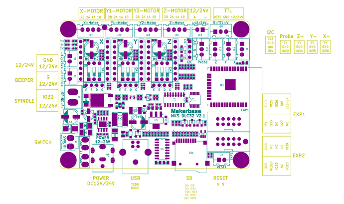
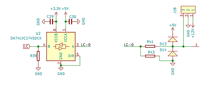
I believe your wiring is a problem at least at this level. Here is the output schematic of the pwm. The J7 and J18 connectors are listed in the above board layout.
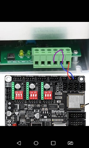
You have J7-1 (yellow) wired to ground, this does nothing, remove it.
A common ground between the board and lps is required. Move J18-2 (ground, blue) to G of the lps, this will create a common signal ground.
J18-3 (pwm, red) wired to IN of the lps. This should be ok…
I assume you have a laser enable or laser power switch… this should go to TL, pulling it to ground will enable the laser.
Make sense?
Sing out if you have issues… or it’s not clear…
![]()
Yes, you need to pull TL low to enable the laser… This is usually a switch on the console…
WP input is usually used for a coolant sensor, in normal operation. I really suggest you put one on your machine. You will goof and run it without coolant one day…
![]()
may I ask you to describe how to pull TL low with schematic?
I found something bro,I measured the output voltage of s pin(J18-3) at 100 percent power and the voltage is 3.22 volts It shouldn’t be 5 volts at 100 percent?
It’s very possible that the board uses 3.3V CMOS logic as the output for PWM. Test the voltage at 50% power. Is it roughly 1.7V? If so, this is probably the case.
If you have a scope then just confirm duty cycle at 100% power.
The lps depends on a DC voltage from 0 to 5V, if the pwm at 100% only gets to 3.3V, there is, most likely a configuration problem… Assuming the hardware is working.
Referring back to the schematic in post 4 … I left out the voltage translator as I didn’t think is was needed at the time.
From this data sheet…
The 74LVC1T45; 74LVCH1T45 are single bit, dual supply transceivers with 3-state outputs that enable bidirectional level translation
I’d double check the setup for S Value Max and $30…
Good luck
![]()
Good to know. So looks like DLC32 translates internal CMOS to true TTL on the output.
This seems then the obvious issue but I couldn’t think of a typical misconfiguration that would account for the difference.
I changed the S Value Max and $30 between 100 to 20000 but the maximum voltage is still 3.22 volts
If the the board uses 3.3V CMOS logic as the output for PWM it is not a suitable board for laser because it can’t reach at maximum power!
What were the values of these set to when you tested for 3.22V?
This isn’t universally true. PWM is not dependent on actual voltage, only duty cycle. Many diode lasers are perfectly fine working at CMOS values. However, as @jkwilborn has pointed out, your board should support 5V TTL, not 3.3V CMOS.
Also, it’s possible that the LPS depends on 5V as @jkwilborn indicated but I’m not familiar with this. I could see this being true if input was expected to be analog.
I’m reviewing this now on a manual for Cloudray MYJG-40 power supply and I don’t see anything that would indicate that 5V PWM is required.
PWM Control: Requirements of the PWM frequency f ≥20 kHz, amplitude (peak value) ≤ 5V
This seems to indicate that as long as peak voltage is less than 5V that it should work.
What specific LPS are you using?
Also, how are you determining that you’re not getting the correct amount of power from the laser?
Smaller amounts at 100 percent power It reaches to 3.22 volts and Larger amounts for example at 30 percent It reaches to 3.22 and with the increase in power percentage, the voltage remains constant
I use DY-13 power supply(lps)
because 100 watts reci t4 co2 laser tube normally cut 3mm acrylic with 20 mm/s speed and 25 percent power but my reci t4 cuts with 10mm/s speed and 50 percent power!
Actually I was asking about the values of S Value Max and $30. What were those values when you tested?
These values need to be the same for power percentage to work correctly.
Where are you getting the reference settings from? The only thing you should really be looking at is tube current to determine if full power is being demanded since many other factors would impact cut performance.
I set the same value for both
I compared that with the reci 4 that used RDC6442G as motherboard
What are the specific values for those two settings?
Also, if you test power levels at 0%, 50%, and 100% what are the measured voltages?
Is this the exact same hardware other than the controller swap? If so, that would be compelling. And what is the reason for the controller swap?
First things first is determining what’s going on with the PWM voltages. According to the diagram that @jkwilborn provided it seems you should be getting TTL voltages.
However, if for some reason the board does run on 3.3V logic I don’t think this is a lost cause.
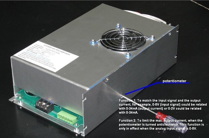
Take a look at this photo from the DY13 manual. It allows you to adjust the LPS to accommodate different range of input voltages.


