at 100% percent 3.22 volts and 50% it is about 1.7 volts
actually my friend has co2 laser cut that works with RDC6442G motherboard and I used mksdlc32 as motherboard but all the hardware are the same I compared my laser function with that
What are the specific values for $30 and S Value Max?
This would be consistent with CMOS values which is interesting.
Are you saying you have like for like hardware or it’s literally the same hardware with the controller swapped?
If the former then these are not directly comparable as there could be other variables in play. I’d highly suggest reviewing current values. You could even compare against your friend’s machine. However, all tubes are tested and rated individually so check for yours.
yes all the hardware are the same except controller
according to TTL input voltage of dy-13 lps which is 0-5V and according to CMOS logic dlc32 which is probably 3.3V is it possible that the low power of the laser might be because of the CMOS logic dlc32 assuming that all the hardware are ok?
Is there a reason you’re not answering the question about $30 and S Value Max? If so, just state it clearly please. If not, can you provide the values?
I suppose this is possible but from what little I can identify about the LPS it should work with PWM.
To me this indicates 0-5V analog and PWM. To me this would mean a PWM signal of any kind as long as it’s under the peak voltage which I assume would be at least 5V. However, it’s possible that they just mean that the LPS is PWM tolerant and really it’s taking the nominal analog voltage no matter what and is scaled between 0-5V.
However, there are now two sides of this that don’t work as advertised:
- DLC32 not providing TTL PWM
- DY-13 not really working with PWM in the expected way
You could likely hack around all this but the concern then is later getting behaviors that are unpredictable.
What revision of DLC32 board do you have? Maybe it’s possible that different revisions don’t get you TTL voltages.
I set $30 to 1000 and S Value Max is 1000 too
If it is possible to use J7-1 which is spindle pin It may solve the problem?
You need to understand these signals… This is getting way out of hand.
This is from the controllers installation wiring or manual.
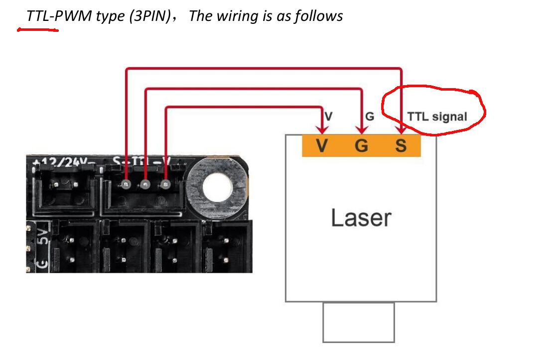
These tell you what kind of signal is generated. Notice it’s a TTL signal.
You won’t because this also works with a dc control voltage. The IN takes whatever comes in, pwm or dc, it changes it to a dc control voltage to drive the current limit circits…
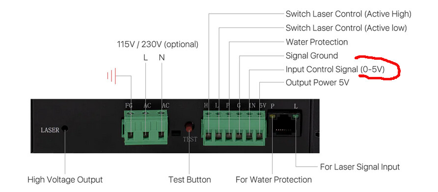
This is an 80W lps from Cloud Ray, it’s control inputs.
Keep in mind history. A variable pwm signal is not a cheap thing to produce if all you have is ttl type devices. They previously (some now) controlled spindles with a 0 to 10V, but 5V ttl made that change.
Today the only way to do it low cost is generate pwm via the micro… so it will accept both, at 0 to 5V
![]()
From one of the diagrams above it looked like J7 was fed from the same circuit as J18. Try measuring the voltage there but I suspect it will be the same.
I’ve seen TTL labeling be abused enough to not necessarily trust that the signaling is actually conforming to TTL. For lasers specifically TTL is often used synonymously with PWM.
There are plenty of systems that allow for analog control voltage but can accommodate true PWM at nearly any voltage. This may not be one of those, however. I just don’t know but the limited documentation is ambiguous at best.
In any case, I suggest @Enzoo validate current at 100% power before proceeding further.
the J7-1 at 100% power shows 12V and at 50% power shows Variable amount of voltage it is not stable at 50%
Maybe with solid state lasers. There is no is no power control per se, just power/time.
I’m trying to help him with an lps/controller for co2. We are trying to control tube current, not just turn it off and on.
If you caught the specification of the input to the lps, it states 0 to 5V which is generally considered ttl.
If he’s reading 3.3V, the best he can get is 3.3V/5V which is 66%.
![]()
If it is possible to use J7-1 which is spindle pin It may solve the problem?
I assume this is going into control circuitry, not directly firing the tube. But perhaps a bad assumption.
How do you reconcile this statement from LPS documentation?
I took that to mean for analog control.
In post 21 I attached a screenshot that shows that the potentiometer in the LPS can be used to accommodate smaller voltage ranges.
This isn’t the standard lps. Mine and the ones I’ve worked with only have 1 adjustment and it’s for maximum current at 5V. If he has one of these, that would be an easy fix. I’ve been around one of the other sites where the K40 lps is common, I don’t remember seeing any external adjustments on them except maximum current. Doesn’t mean they don’t exist.
If you take a dc meter and read a ttl level pwm square wave, at 50% power it will read 2.5V… that is a dc meter reading. We know there is actually 5V there…
You can see how it works… here is a K40 lps schematic, thanks to Don at MakerForum…
These have a low pass filter as the first circuit passes through. These work fine with a 1kHz pwm from an Arduino…
If you mean the ≤ 5V, then someone is elsewhere.
x is 0
If (x ≤ 5)
   On
else
   Off
Don’t think so… it’s not going to turn off until it exceeds the maximum range.
Many of these modules set a period limit of 1mS (1kHz) for the modules… Many I don’t believe…
![]()
The screenshot was taken from the manual for DY-13 which is the model that he has. Also, it looks like to me that there’s only one adjustment and it’s used for both listed functions. I suspect what they’re saying is that clockwise adjustment increases current relative to input voltage (effectively allowing for lower voltage ranges) while anti-clockwise taps current such that 0-5V is constrained to a lower current range.
I’m not arguing against this in case that’s how you’re interpreting it.
Working fine is one thing. I’m only trying to reconcile the documentation. It clearly states that expected frequency is at least 20 kHz. This is one reason I don’t necessarily trust the documentation when it comes to actual specific behavior.
Indeed I was specifically calling out this point.
I interpret this to mean fairly typical PWM control… absolute voltage doesn’t matter as long as it’s above the threshold “on” voltage and only duty cycle being important for control.
Note that this wording was for a different LPS than the DY-13, however (MYJG-40).
So is there any way to get 5V TTL from the controller or I have to change motherboard!?
What board revision do you have? It’s possible that your board is meant to have 3.3V output.
If that’s the case, then my suggestion would be:
- confirm the tube current at 100% power. Actually, it’s probably safer to run at 80% power and extrapolate projected 100% power current. You want to make sure you’re not actually already driving at max current and have other reasons for getting different performance than expected.
- if you can confirm that you’re not getting peak expected current then adjust potentiometer on the LPS as shown in the earlier attached photo to adjust for 0-3.3V range.
This is the problem… this is not digital it’s analog, it uses a resistor/cap filter to change this into an average dc voltage. If dc is applied there is no change…
This is the failure of most K40 connections. They use the pwm to turn the tube on and off at the pot set dc voltage. When it lases, it lases at the 100% current, set by the pot.
With this, the IN voltage can be set at 2.5V with dc or a 50% pwm. When L goes low it lases at 50% power.
The L or H inputs work the way you describe, but not the IN
I think the board is probably ok, they are pretty tough. Chances of that component failing and exposing 5V to the internal 3.3V seems unlikely.
I think we are missing something with the configuration. Maybe the SD card? I will have to break mine out and check, but I used it before I changed firmware and the pwm was a ttl level signal, as expected.
Makes me wonder why they would have a pot to adjust it down to 2V? I think it’s just a range compression with full left being off (zero resistance) or allowing a 0 to 5V range. Wonder where/why this is there. The originals were only 5V as far as I know.
Do they say in there why you would do this?
![]()