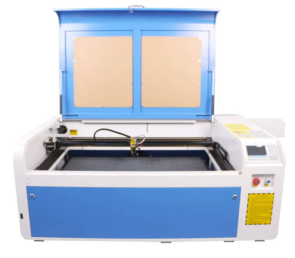
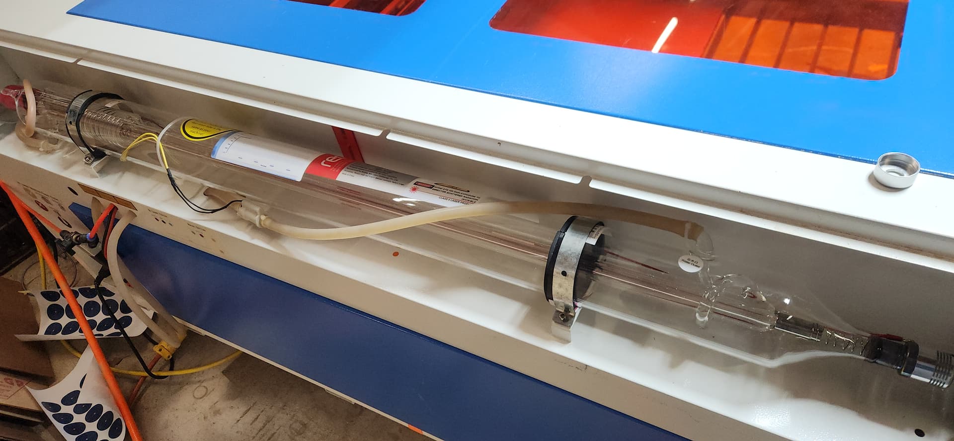
I recently replaced the CO2 tube on my 100W laser (image below) and re-calibrated the machine by aligning the mirrors. The beam hits the same spot at near and far distances on the gantry, and it enters the head at the center. However, it exits the head at a severe angle.
When cutting 1/4" acrylic squares, 3 out of the 4 sides are not straight. I’ve tried adjusting the mirror on the head (shooting into the lens), but it didn’t resolve the issue. Next, I experimented with adjusting the beam’s entry point into the head slightly above and to the left of center. This reduced the beam angle coming out of the tip and improved the cuts, bringing them closer to 90 degrees.
My main question is:
Why does the beam need to enter the head off-center to reduce the angle of the output beam?
Generally speaking, the beam should go down the center of all the optical paths. However sometimes in the real world it doesn’t work out so great. So a more general statement is the should be as close as possible to the center on both m1 and m2.
On one like my original, being in the center of the mirror is not the center of the down tube and lens. So m3 may end up not centered.
You have to move the head in the Z direction to move the spot along the X axes and you need to be able to move m2 in the Y direction if you want full adjust ability. Most of these do not allow these adjustments, so you do your best with what you have. The beam needs to enter the lens centered, if it’s at an angle it will come out at an angle.
How did you do this? Do you have targets on the work area or at the end of the lens tube?
This makes me think you have the lens sitting crooked or something else occurring within the head. Usually if you miss it inside the lens tube heats up as the energy has to go somewhere.
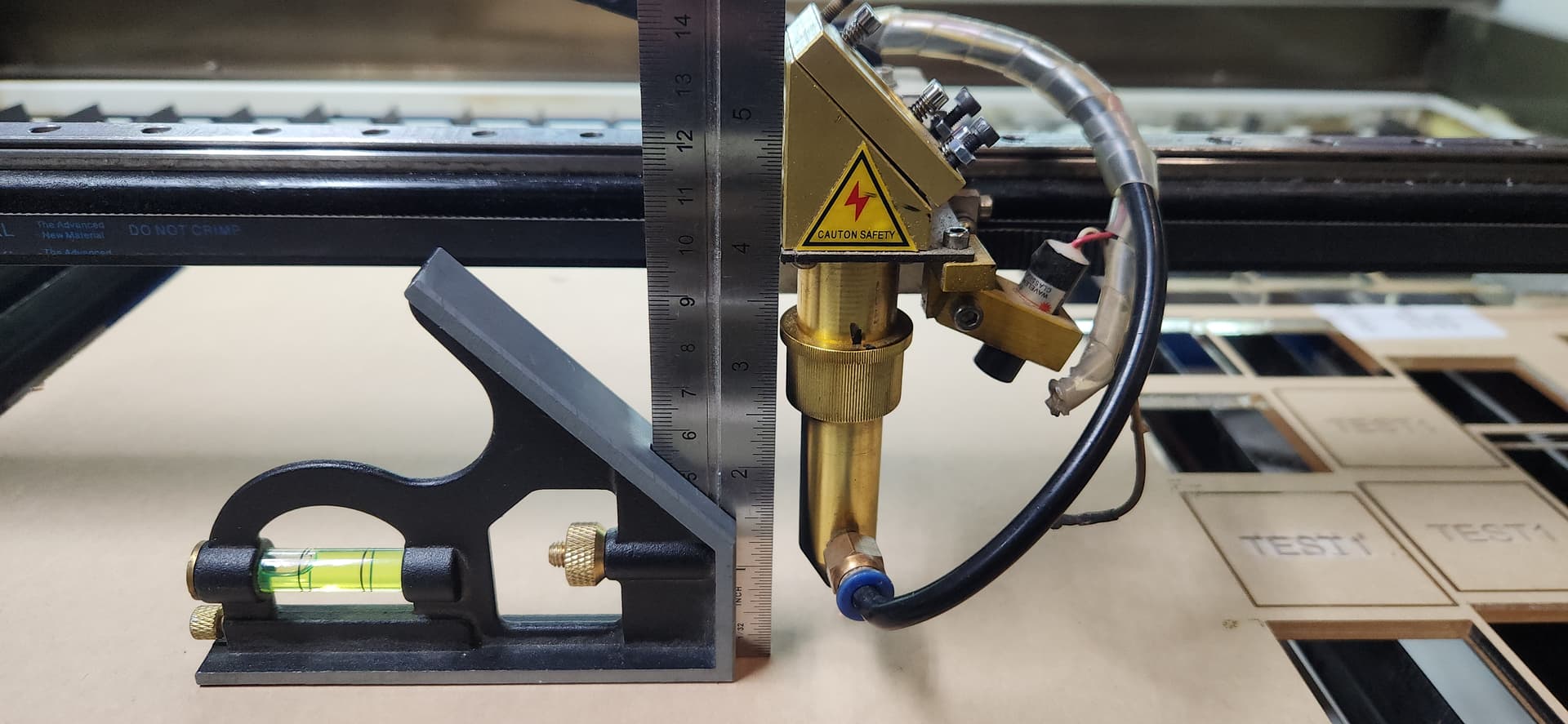
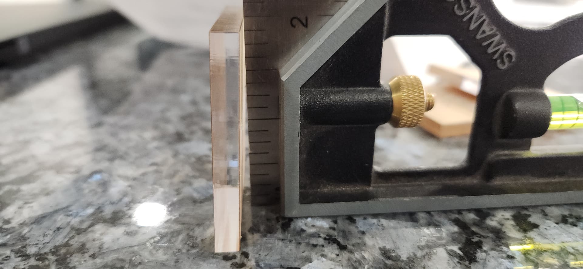
So, if I understand what you mean by vertically, I took a look at how square the head is based on what @Dannym said and it seems pretty squared up. I placed a piece of acrylic on the table and set my square on that (see pics).
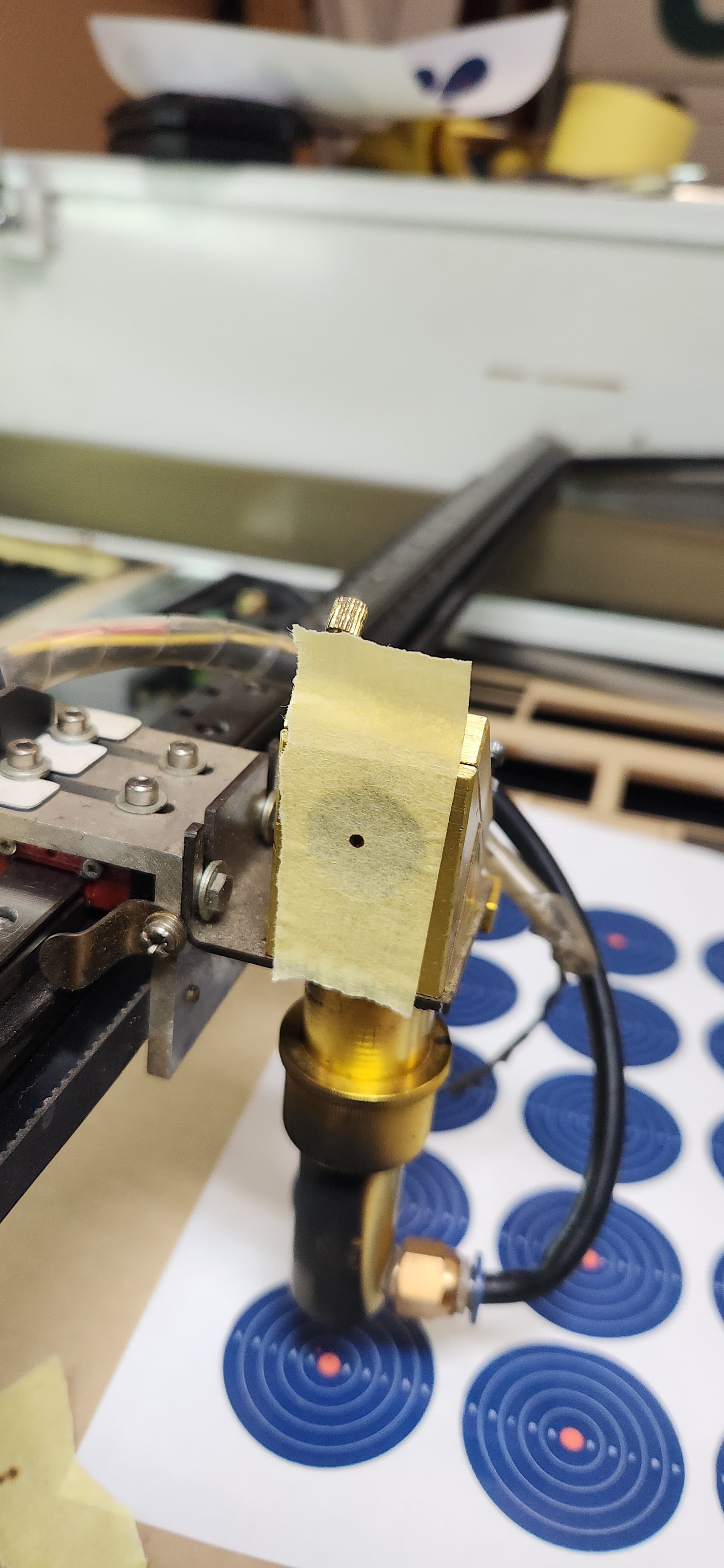
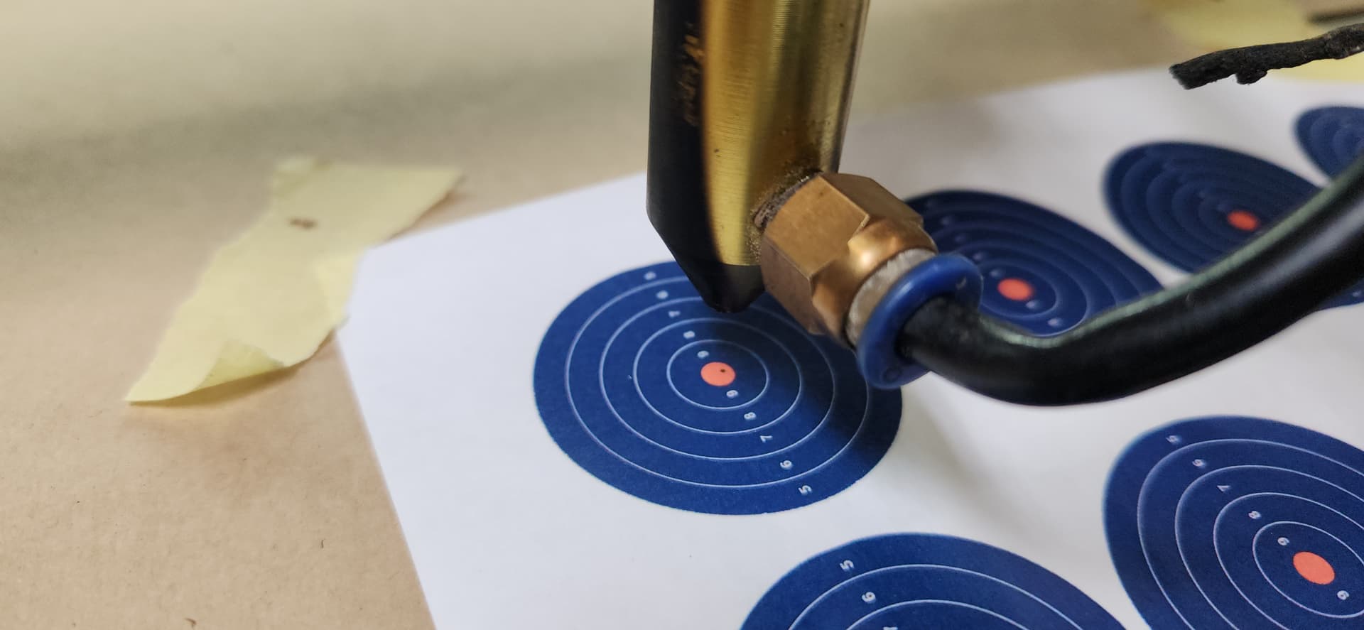
Finally I printed out some bullseyes from @soniclab comment. I lowered the head down until I could line it up with the center of the target and then adjusted the head mirror to center the beam. (beam not centered in this pic but was centered after)
I finally cut a test piece and am still getting slanted cuts. It seems like 1 side is really rough, two sides are slightly slanted, and one side is typically mostly straight.
Hopefully this extra info is helpful. @jkwilborn I’ll work on centering the beam from mirror 1 to mirror 2 to see if it helps when it goes into the head. But I think the issue might be between mirror 2 and mirror 3
I can’t really tell if its on a major slant or not. I used the original padding/shims that were on the original tube and adjusted the rightmost padding with shims to get it to line up centered with mirror 1.
The tube mounts are welded metal and dont allow for any adjustment other than using shims underneath the tube. Is there a good method to check for slant?
If it’s out a bit, it’s fixable via the mirror adjustments. The tube doesn’t need to be absolutely square, as long as the last mirror is fixed. If it did, none of us could replace our tubes.
–
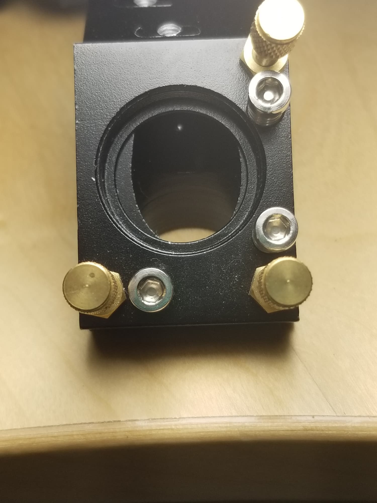
This is your first photo, figure it’s m1 as the tubes cathode is at the bottom. It doesn’t look round to me… does it to you?
Is the beam is hitting the same off-center spot in front and back? If so, the #2 mirror is offset. Its mount must be moved to the right by a few mm.
If nothing else is changed, that action of a pure offset move to the right on #2 will also offset the beam slightly to the rear even with perfect angular alignment making it parallel to the gantry rails. If this is wrong, then you also need to offset the #2 mirror mount to the front of the machine to move the beam line.
Yes it’s a bit of a juggling act, made complicated because not only is there not a fine adjusting screw to set the offset, once you loosen the screws then the angle is going to go wild and it’s difficult to see what you’re doing.
I’d recommend that you begin an offset adjustment by “resetting” #2. Look at the plate that tilts on the 3 screw points. Adjust all 3 to make that plate parallel to the mount and basically shoot for being midway of the spring travel.
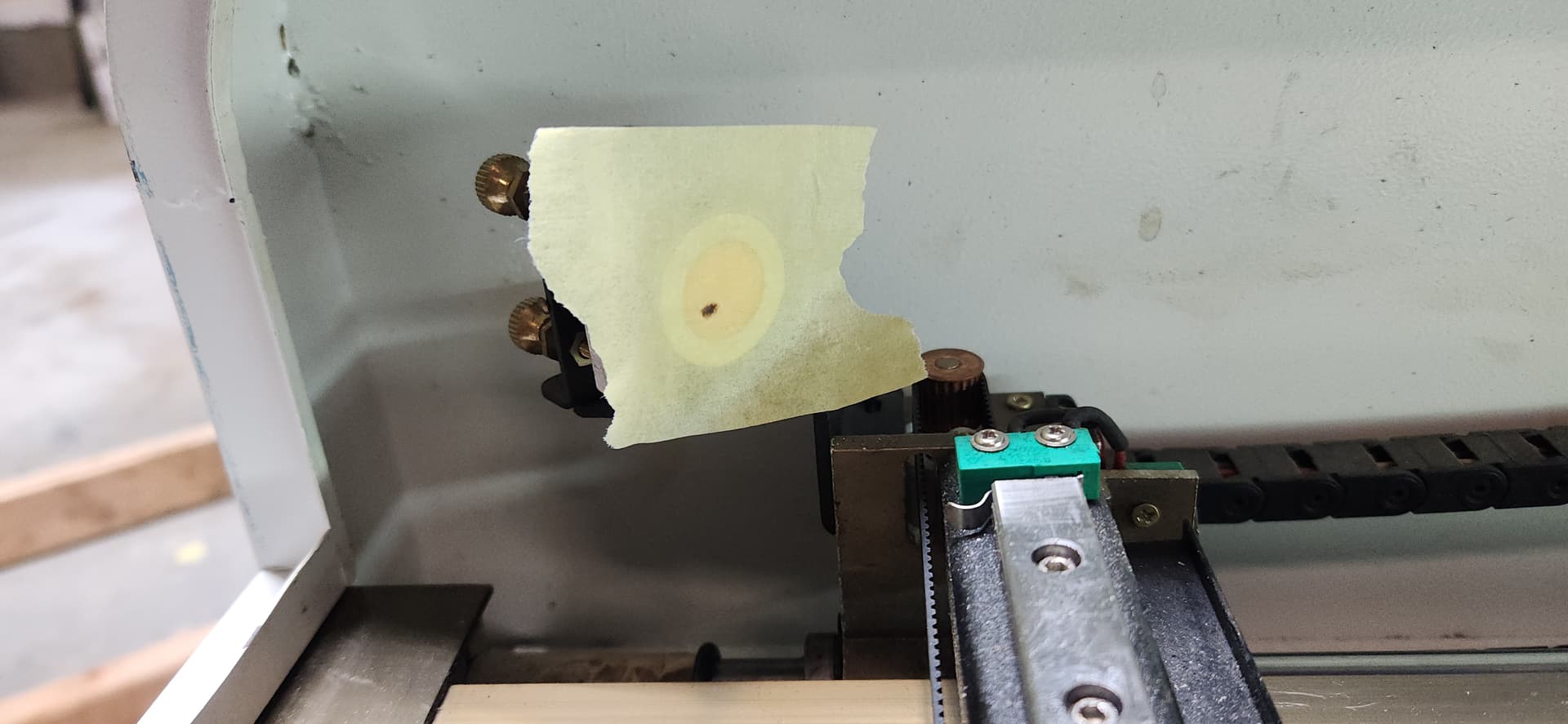
Hoping you have a red dot, it makes this easier- get the dot on, jog the head to the left. Put tape over #2. Move the mirror L/R to get the red dot basically in the center. Don’t bother firing it, it is not very helpful and contaminates the mirror.
Pull the tape off #2 and put tape on the aperture into the head. Head should still be on the left of the bed, at this point it is much less sensitive to angular adjustments. Is the beam centered on the head aperture? If it’s too far front/rear you’ll need to offset the #2 mirror mount.
Move the head to the right, get the angle adjusted to hit the head aperture dead center with the head on the right. Jog back to the left. Hopefully it’s still dead center. If not, you need to make another pass at getting the #2 offset correct. Repeat until good
To measure angular error:
Find the thickest acrylic you can, cut a bar like 1/2" wide 24in long.
clamp a physical straightedge onto the bed, going left/right, and check/adjust to make it parallel to the gantry.
Align the bar with the straightedge, slide it so the head will cut like 1/4" off the left edge, with the cut line going front/back.
Mark the last 3/4" of the bar “TOP” on its top, and “LEFT” on the left side. It would be best to just raster that text into this part initially along with the first cut. Flip the bar over and cut this 3/4" off the left.
Then you will have either a correct rectangular cross section, or a trapezoid. You won’t have a parallelogram, that’s not possible because we flipped the bar and reversed the angle. You can measure the difference in the width of the top vs bottom of the trapezoid to get the magnitude of the correction. The “TOP/LEFT” marking will track which direction the correction needs to go.
Rarer, but possible, there can be an angle error front/back too. You’d basically do the same test with the straightedge parallel to the Y axis and test cut left/right. More difficult to adjust, you might loosen the XY joints on L/R and insert shims. It is possible for a gantry to be twisted too
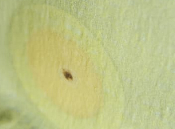
I usually check the angle by pulsing a spot at the correct focus height, and then lower the table further by at least another couple of inches, and then pulse again, the two pulse spots should be concentric for straight cuts.
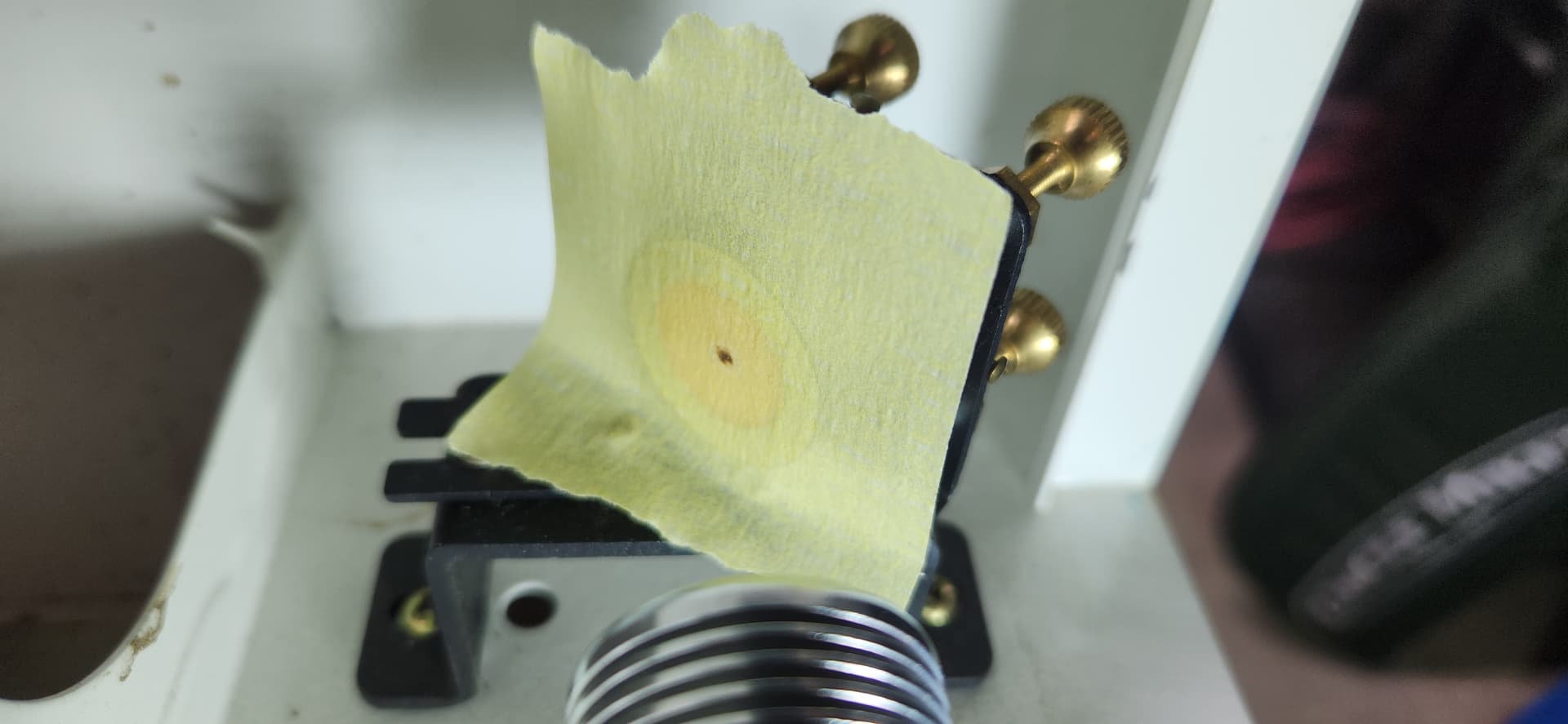
If you find that you need to make corrective adjustments to the head mirror, afterwards you will need to check again if the spot is still centered as it exits the laser nozzle (masking tape over the end of the nozzle and press to leave an indent so after pulsing, when you peel the tape off you can see how centered that spot is).
It’s working! I ended up performing the alignment process from scratch and what I found was that after swapping in the new tube, the height from the head to the bed needed to change from previous. I might end up returning the tube due to the beam not being completely circular from tube to mirror 1, but so far so good with my cuts. I’ve learned some new ways to align/calibrate the laser though. I’m getting 90 degree cuts and they’re looking good! Thanks all for the help! You’re all a wealth of information.
The platform leadscrews may not be precisely concentric, so the whole affair can wobbulate in the XY plane. My OMTech can move by a millimeter during one leadscrew rotation, which means the scorches don’t quite line up:
That is definitely something to be aware of, thankfully most of the machines I’ve worked with are well built and don’t have enough wobbulation to worry about