I recently purchased and installed Laserboard and Cohesion3D Rotary on a 50w Yellow and Black laser that previously had an M2 Nano board. So far the only issue I’m having I can’t get Lightburn 0.9.07 to properly work with the Cohesion3D Rotary.
I’ve followed the setup instructions and settings and when I enter G0 A360 F120 the wheel on the rotary does turn 360 degrees an seems to be working fine. But, when I try to engrave a 10x10mm square on a piece of dowel, it always engraves the same size square of about 10x8.5mm … this happens no matter what I change the Object Diameter size to in Lightburn. The square always comes out with the same proportions, no matter if the Object Diameter set to 90mm or 900mm. Am I missing something here?
Did you click the ‘Enable’ button? Changing the object diameter does nothing with a roller rotary, but you do need to have the roller diameter set correctly. Make sure you have that set, and have enabled the toggle to turn on rotary mode.
Yes, the 'Enable’ button is on. The rotary works (turns) when I enable the rotary button, when disable the rotary button, the laser head moves in the “Y” direction instead of the rotary rotating, so it looks like things are working correctly.
“Roller Diameter” is set to 50mm as per Cohesion3D specs and I’ve double-checked this with my calipers.
Also, the config file is set up to Cohesion3D specs. I’m not sure what else to check here.
I just tested an older version of LightBurn and also have tested both bitmap and vectors shapes and I get the same results.
Are you using Fill or Line mode with this, and are you running inches or mm as your units in LightBurn?
I’m using Line mode. I’ve also tried a 10x10mm raster square with the same results.
I’m running in mm for units.
When you said you set up the rotary, and using the G1 A360 command, it turns 360 degrees, how did you verify that? If the steps per degree setting was off, it would throw everything else off too.
I placed a mark on the wheel and a corresponding mark on the rotary frame. I issue the command and get a full 360 degree turn on the wheel.
It seems like the board isn’t receiving the correct “Object Diameter” or “Circumference” number from Lightburn and it stuck on a default number. No matter what I change the “Object Diameter” too, the square stays the same size. If I had to guess, it’s stuck on a diameter somewhere around 20-25mm.
Note that I just tested this on an older version of Lightburn I had on a different computer and I get the same results, only the rotary settings reset themselves to Lightburn’s defaults after I close the rotary options window.
The board doesn’t use those, only LightBurn does - they’re stored in the preferences and used to alter the generated GCode. Are you running the file from a different system than you’re creating it on? Have you chosen the A axis?
No, I’m simply creating a circle of square in Lightburn and sending it to the machine as Line.
I’ve set it up the on the A Axis as per the manufactures instruction for using it with LightBurn: https://forum.cohesion3d.com/t/rotary-setup-on-laserboard/776
I’ve tested this myself, with a different rotary, but using the same 2:1 reduction and a C3D Laserboard. My steps per degree, computed before I looked at the post you linked, is 17.77776, and I set up the steps value accordingly.
In the ‘Move’ window, I can rotate the A axis 360 degrees and it’s perfect - I marked the rotary wheel with tape, and pointed a pen at the corner of the mark, rotated it multiple full revolutions in the same direction, and each time it stopped at the exact same spot.
My rotary has wheels that are exactly 54.25mm in diameter. I put a spray can on the rotary that I measured at 66mm in diameter. I entered those values and the software tells me that the circumference in 207.345mm:
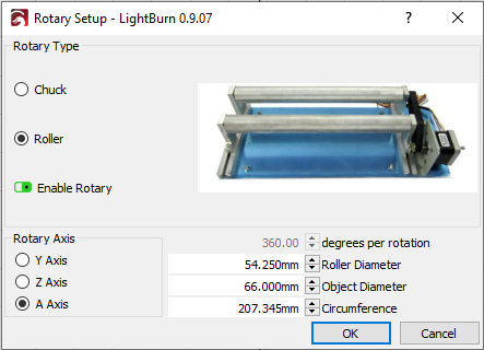
I created a rectangle in LightBurn that is 207.345mm tall, set it to run as a line. I put a black mark on the rim of the can and pointed a pen at it, and this is the result:
You can see it makes one full rotation, then returns, and both times the black mark stops in the same place.
So, it does work for me, and I’m not sure why it doesn’t for you - I’m hoping that by walking through all of this perhaps it’ll jog something for you that you might have done differently.
Thanks for going through all that.
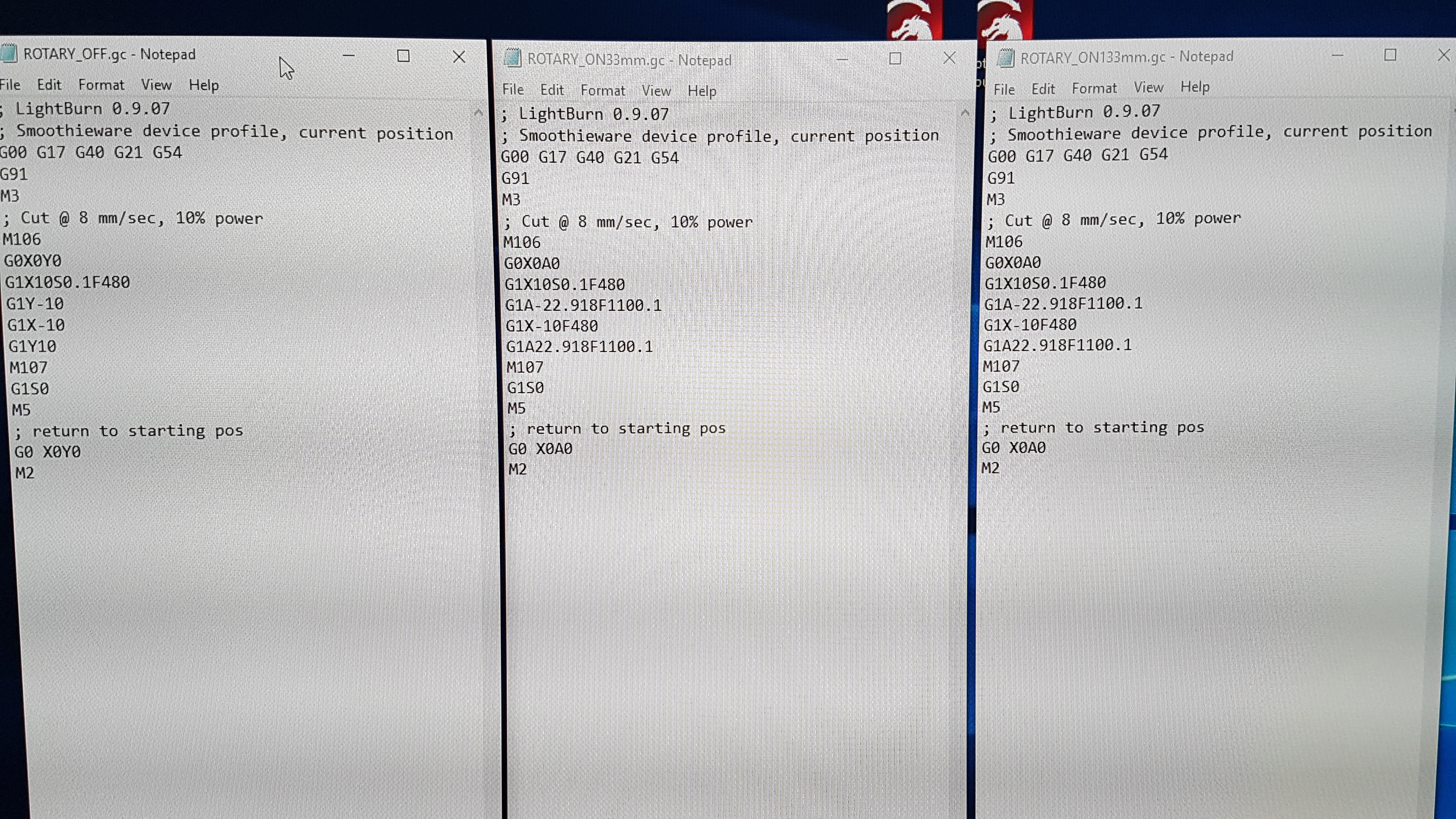
After more troubleshooting, I THINK this is a Lightburn issue. Please look at the Gcode image and you’ll see 3 gcode’s produced by Lightburn side by side. The first is with the rotary option off, the second is with the rotary tool on a and set to an object diameter of 33.50mm and the third is with the object diameter set to 133.50mm. As you can see, the codes for the second and third are the same, leaving me to believe that Lightburn isn’t changing it’s “object diameter” variable and is stuck on some sort of default.
All of these were done using the same 10mmx10mm square and nothing else changed.
You have a C3D rotary, which uses rollers, not a chuck. The ‘Object Diameter’ value in the rotary setup is only there to show you the circumference needed to get a full wrap - it has absolutely no effect on the motion of the rotary itself. Only changing the roller diameter or degrees per rotation would affect the GCode, so what you’ve posted is working exactly as it should.
Your code also shows moves of 22.918 degrees on the rotary axis.
If your wheels are 50mm in diameter, that means that the circumference of those wheels is 50mm * PI, or 157.0796mm around. Dividing that by 360 gives 0.436 mm of surface travel per degree.
Multiply that by 22.918 and you get 9.99986mm - damn close to the 10mm you asked for. So the math is right, assuming your numbers are right. (If we go up to 22.919 degrees it comes out to 10.000300mm, so 22.918 is closer than 22.919, and LightBurn is rounding to 3 decimals to keep the gcode reasonable)
Sorry, I’m I must be missing something very basic here, so please bear with me.
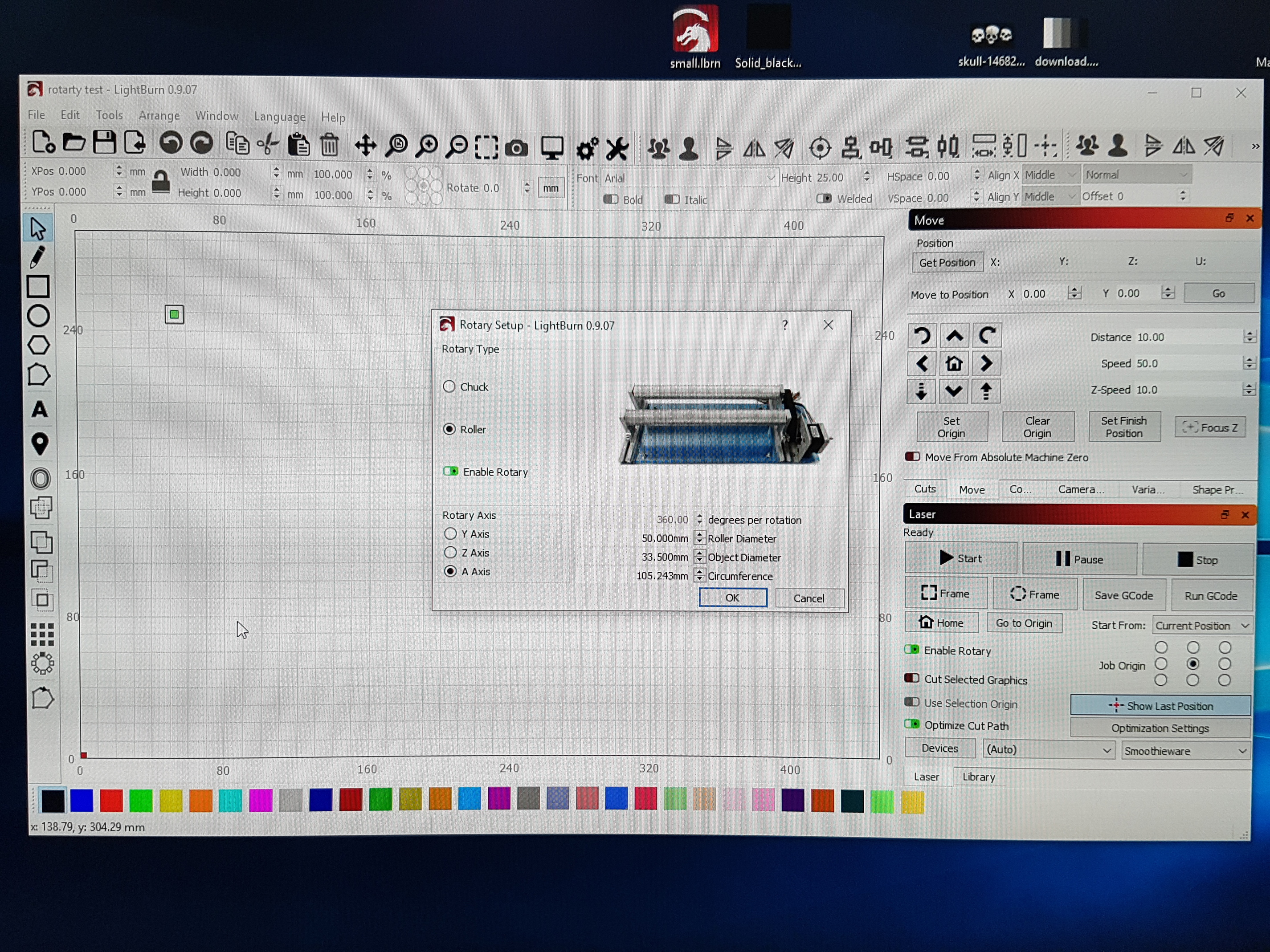
The second and third Gcode’s are of an Object Diameter of 33.5mm and 133.5mm respectfully. Entering this automatically changes the circumference in the rotary panel. Should this not also change the Gcode and as you now have two different circumferences?
Here’s how it’s setup:
What is it that you expect to see changing by changing the object diameter, exactly?
If you want to engrave a 10mm square on a Coke can, the rollers move 22.918 degrees, moving the surface of the rollers 10mm, and transferring that motion to the Coke can.
If you put a dowel on there instead, the rollers still have to rotate 22.918 degrees to move the roller surface 10mm, to transfer that motion to the dowel. The diameter & circumference of the dowel or Coke can are irrelevant - You’re driving the rollers, and they are driving the object.
If you were using a chuck rotary, where the stepper motor was directly affecting the angular orientation of the object, then the object diameter matters. As the diameter got larger, you would rotate the object by fewer degrees to travel the same surface distance, but since you have rollers, you’re rotating them, and they rotate the object, so it doesn’t matter.
1 Like
This topic was automatically closed 30 days after the last reply. New replies are no longer allowed.